System and method for loop detector installation

a loop detector and installation system technology, applied in the direction of machine supports, coupling device connections, electrical apparatus casings/cabinets/drawers, etc., can solve the problems of inoperable travel lane for a considerable time, difficult control of the position of the sensor within the groove web, and inconvenient connection, so as to minimize time and installation effort and facilitate connection

Active Publication Date: 2011-05-31
TRANSCORE
View PDF124 Cites 8 Cited by
  • Summary
  • Abstract
  • Description
  • Claims
  • Application Information

AI Technical Summary

Benefits of technology

[0014]In some embodiments, the loop sensor housing when fully assembled assumes a cross-sectional shape and size adapted to easily fit within pre-cut grooves in a road surface layer.
[0020]In some embodiments, the loop sensor housing may include a deformable side portion that holds the housing in place when inserted in a groove. In some embodiments, the deformable side portion is configured in an initial size larger than a groove width into which it is placed, and is substantially deformable so that the housing fits snugly within the groove after placement. The loop sensor housing may further include a top retaining portion (or “lip”) that extends over a surface into which the grooves are cut, providing further stability for the prefabricated loop sensor, and assuring that ferromagnetic loop wires within the housing are located at a fixed distance from the road surface, once the loop sensor is inserted into a groove.
[0021]In some embodiments, the pre-fabricated loop sensor may include a connector extending from one region of the loop sensor wires, to provide easy connection to a loop detector used to process signals generated by the loop sensor.
[0022]Accordingly, the pre-fabricated loop sensor of the invention can be quickly fitted into place and rendered operational in a precut groove web having a predetermined ferromagnetic loop sensor pattern, thus minimizing time and installation effort in the “field.”

Problems solved by technology

The above procedure can entail considerable time and difficulty, causing a travel lane to be inoperable for a considerable time.
In addition, control of position of the sensor within a groove web can be difficult.
Inadvertent variations in the sensor loop wire depth incurred in the above process during wire laying, can cause unwanted changes in the loop properties.

Method used


Image

  • System and method for loop detector installation
  • System and method for loop detector installation
  • System and method for loop detector installation

Examples


Embodiment Construction

[0052]Elements of the ferromagnetic loops of the invention include the magnetic strength of flux field height and length. The shallow installation of wire and wire orientation of the coil in loop installations is important for optimal performance of the ferromagnetic loop design. The flux field created by the loop circuit is concentrated and low to the road surface to maximize the ferromagnetic effect of the wheel assemblies and minimize the eddy currents created by vehicle chassis.

[0053]As discussed in the '972 application in detail, the geometry of the loop wire turnings in a prefabricated loop sensor can be oriented in different directions relative to the direction that vehicles travel in order to vary the response of the loop sensor to the vehicle wheels. Accordingly, prefabricated loop sensors of the present invention can assume any designed geometry, including those designed to produce a specific response.

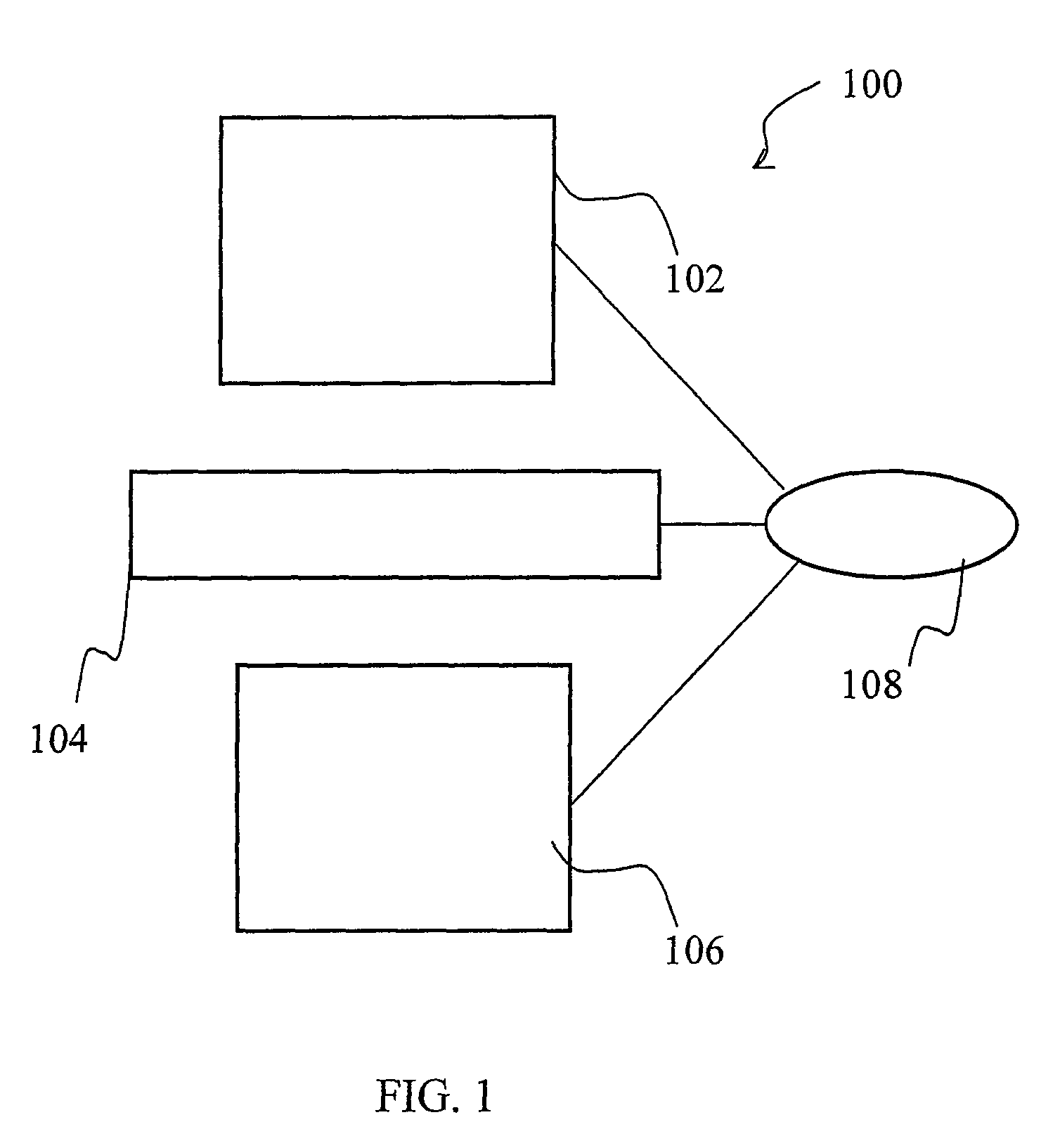
[0054]FIG. 1 illustrates a plan view of a loop sensor system 100, config...


PUM


Abstract

A pre-fabricated ferromagnetic loop having a footprint characterized by a continuous wire shaped according to a predetermined planar pattern. In some embodiments, the predetermined planar pattern can be multiple contiguous polygons within a larger footprint used for establishing a sensor for the detection of moving vehicles. The footprint may include one of a triangle, a square, a rectangle, a rhombus, a parallelogram, an ellipse, or a circle, and / or other shapes or configurations. Similarly, each of the multiple contiguous polygons may include one of a triangle, a square, a rectangle, a rhombus, a parallelogram, and / or other shapes or configurations. A loop sensor housing is arranged to enclose a continuous loop sensor wire configured in the predetermined planar pattern. The prefabricated loop sensor is inserted in a groove web pre-cut in a receiving medium to match the predetermined planar pattern.

Description

RELATED APPLICATIONS[0001]This application claims the benefit of U.S. Provisional Patent Application Ser. No. 60 / 915,886, entitled “System and Method for Loop Detector Installation,” filed May 3, 2007.BACKGROUND[0002]1. Field of the Invention[0003]The invention relates generally to detection, identification, and classification of metallic objects, and more particularly, to a system and method for efficient installation of ferromagnetic loops on traveling surfaces.[0004]2. Background of the Invention[0005]Applicants reference U.S. patent application Ser. No. 10 / 953,858, filed Sep. 30, 2004 (“the '858 application”), which is a continuation of U.S. patent application Ser. No. 10 / 206,972, (the '972 application, now U.S. Pat. No. 6,864,804), which is a continuation-in-part application of U.S. patent application Ser. No. 10 / 098,131, filed Mar. 15, 2002 (“the '131 application”), which is a continuation-in-part application of U.S. patent application Ser. No. 09 / 977,937 (“the '937 applicatio...

Claims


Application Information

Patent Timeline
Patent Type & Authority Patents(United States)
IPC IPC(8): H05K5/00
CPCG08G1/02Y10S248/906
Inventor ALLEN, JIM
Owner TRANSCORE
Why Eureka
Try Eureka