Range gated holographic radar

a holographic radar and range gate technology, applied in the field of radars, can solve the problems of inability to use, severe restrictions in the operation of high-bandwidth radars, and limited ism bandwidth, and achieve the effect of low noise range and high spatial resolution

Inactive Publication Date: 2011-05-31
MCEWAN TECH
View PDF37 Cites 68 Cited by
  • Summary
  • Abstract
  • Description
  • Claims
  • Application Information

AI Technical Summary

Problems solved by technology

Operation of these high bandwidth radars is severely restricted by regulatory agencies such as the FCC.
Examples of these restrictions include: (1) UWB radars in the U.S. can only be operated outdoors with extremely limited radiated power levels and only when handheld; (2) wideband tank level sensing radars can only be operated inside tanks, and cannot be used to sense river levels, for example; and (3) ISM bandwidth is very limited, such as the 50 MHz wide 10.5 GHz band.
While high bandwidth radar is subject to severe regulatory limitations, operation without a range-gate introduces other severe limitations.
The lack of a range gate may be ideal for police speed-sensing radar, but it is completely undesirable for security alarms; a person moving outside a protected zone could false-rigger an ungated radar.
Numerous range-gated motion sensing radars exist in the prior art; yet they often require high bandwidths and are thus subject to tight regulatory restriction.
However, the radar is a CW radar and has no range gating.
Thus, the holographic image can be contaminated by echoes from outside the image plane.
It is only practical in situations where the clutter scene can be tightly controlled.
Further, it can only work with objects that are not semi-transparent to radar; e.g., forming a holographic image of a wood or plastic surface could be difficult if not impossible.

Method used


Image

  • Range gated holographic radar
  • Range gated holographic radar
  • Range gated holographic radar

Examples


Embodiment Construction

[0031]A detailed description of the present invention is provided below with reference to the figures. While illustrative component values and circuit parameters are given, other embodiments can be constructed with other component values and circuit parameters.

General Description

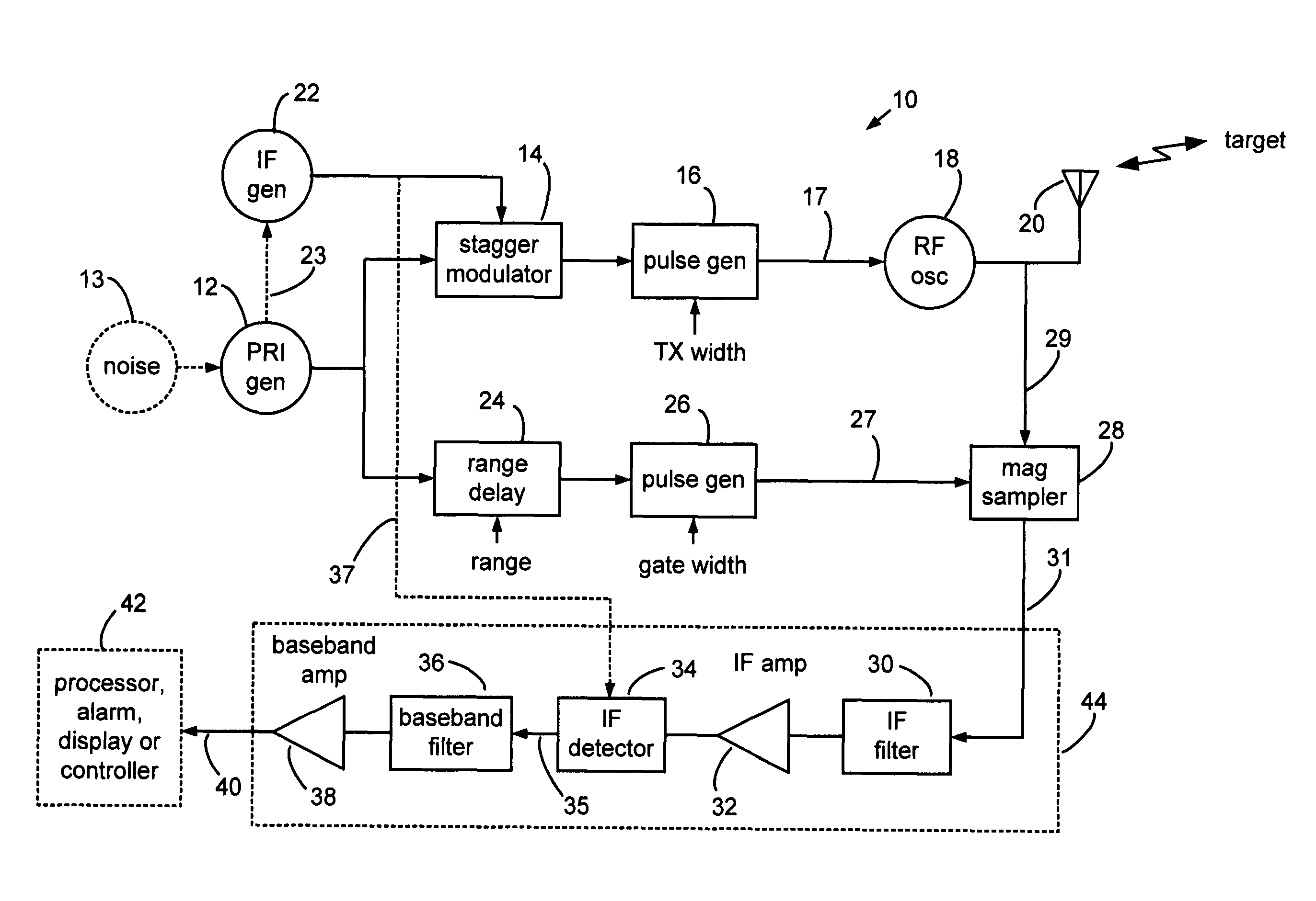
[0032]The present invention overcomes the limitations of prior art holographic radar by introducing a range gate to limit response to a specific downrange region. Consequently, cleaner, more clutter-free radar holograms of an imaged surface can be obtained, particularly when penetrating materials to image interior image planes, or slices. Range-gating also enables stacked hologram technology, where multiple imaged surfaces can be stacked in the downrange direction. Holograms of interior slices of a solid object can include slices of a tree, interior slices of human organs, and depth-wise slices from ground penetrating holographic radar, such as holographic images of buried tombstones.

[0033]The present invent...


PUM


Abstract

Narrow virtual transmit pulses are synthesized by differencing long-duration, staggered pulse repetition interval (PRI) transmit pulses. PRI is staggered at an intermediate frequency IF. Echoes from virtual pulses form IF-modulated interference patterns with a reference wave. Samples of interference patterns are IF-filtered to produce high spatial resolution holographic data. PRI stagger can be very small, e.g., 1-ns, to produce a 1-ns virtual pulse from very long, staggered transmit pulses. Occupied Bandwidth (OBW) can be less than 10 MHz due to long RF pulses needed for holography, while spatial resolution can be very high, corresponding to ultra-wideband (UWB) operation, due to short virtual pulses. X-Y antenna scanning can produce range-gated surface holograms from quadrature data. Multiple range gates can produce stacked-in-range holograms. Motion and vibration can be detected by changes in interference patterns within a range-gated zone.

Description

BACKGROUND OF THE INVENTION[0001]1. Field of the Invention[0002]The present invention relates to radar and more particularly to interferometric and holographic radar. The invention can be used to form holograms, to form stacked holograms, to detect motion and vibration within a gated region, and to find range.[0003]2. Description of Related Art[0004]Pulse echo and FMCW high resolution radars typically have emissions that are wideband to ultra-wideband (UWB). UWB impulse radars emit short pulses of ½ to one RF cycle in duration, with corresponding bandwidths extending from 500 MHz to 10 GHz or more. Wideband pulse-echo radars emit bursts of RF sinusoids; tank level sensing radars typically emit 10 to 20 RF sinusoids in a burst with a corresponding bandwidth of greater than several hundred megahertz. Similar bandwidths pertain to high resolution FMCW radars. Operation of these high bandwidth radars is severely restricted by regulatory agencies such as the FCC. Examples of these restri...

Claims


Application Information

Patent Timeline
Patent Type & Authority Patents(United States)
IPC IPC(8): G01S13/22G01S7/483G01S13/18G01S13/00
CPCG01S13/18G01S13/89G01S13/225G01S13/0209G01S13/62
Inventor MCEWAN, THOMAS EDWARD
Owner MCEWAN TECH
Why Eureka
Try Eureka