
System and method for in-flight adjustment of store ejector gas flow orificing

a technology of in-flight adjustment and orifice, which is applied in the direction of launching weapons, actuating automatically, spars/stringers, etc., can solve the problems of missile loss, aircraft and crew loss, and failure of weapon deploymen

Active Publication Date: 2011-06-07
THE BOEING CO
View PDF11 Cites 16 Cited by
  • Summary
  • Abstract
  • Description
  • Claims
  • Application Information

AI Technical Summary

Benefits of technology

Enables precise and adjustable pitch control of ejected stores, improving the safety and accuracy of store separation by aligning with actual flight conditions, reducing the risk of store failure and aircraft damage.

Problems solved by technology

In the case where the store is a weapon, such problems can result in failure of the weapon to deploy.
Improper store separation can also result in tumbling of the store which may compromise the functionality of guidance systems contained within the store and which serve to guide the store to a target.
An ejection of the store that results in a tumbling of the missile may result in the loss of the missile.
In extreme cases, improper store separation may result in the store striking the aircraft which can result in loss of aircraft and crew.
Unfortunately, such metering arrangements are only adjustable on the ground prior to flight and must be set according to the flight condition (e.g., speed, altitude, pitch, acceleration) of the aircraft that is predicted to occur during release of the store.
Once airborne, if the actual flight condition at time of store release differs from the predicted flight condition, the store may eject with an improper pitch attitude.
As mentioned above, such improper pitch attitude of the store may result in failure of the store (e.g., weapon) to deploy correctly result in loss of the weapon and / or loss of the aircraft should the weapon strike the aircraft.

Method used


Image

  • System and method for in-flight adjustment of store ejector gas flow orificing
  • System and method for in-flight adjustment of store ejector gas flow orificing
  • System and method for in-flight adjustment of store ejector gas flow orificing

Examples


Embodiment Construction

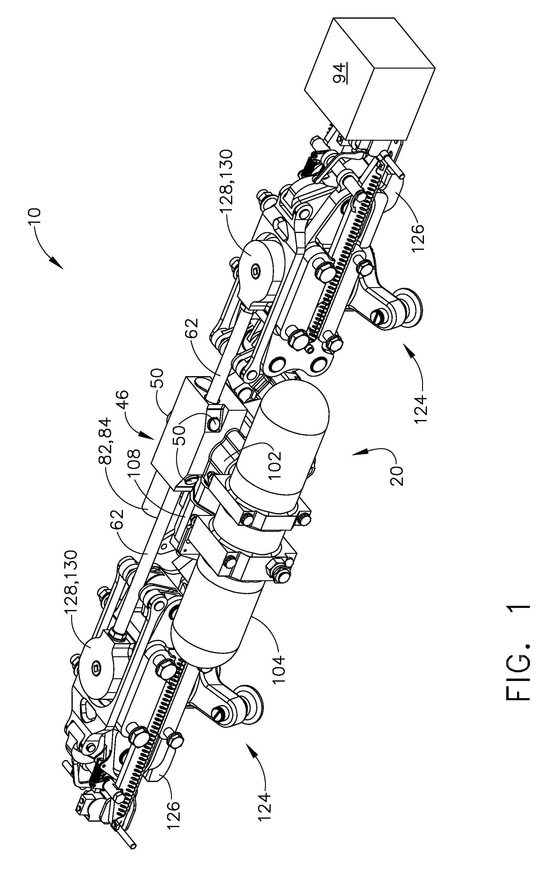
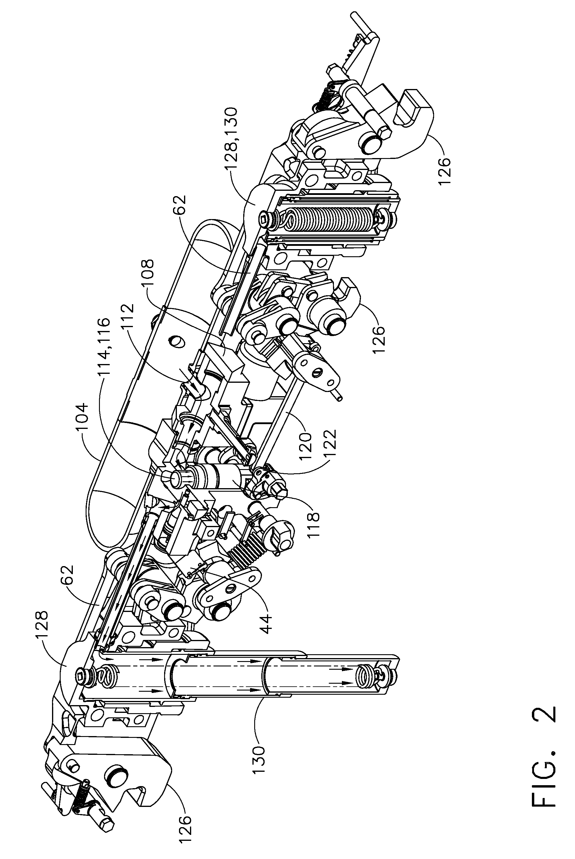
[0031]Referring now to the drawings wherein the showings are for purposes of illustrating preferred and various embodiments of the invention only and not for purposes of limiting the same, FIG. 1 is a perspective illustration of a store ejector 10 such as may be mounted on an aircraft and wherein the store ejector 10 may include an in-flight adjustable orifice assembly 46 and a VPVC 94. At the time of store 12 launch, the VPVC 94 receives information such as store release pitch data from a flight computer 14 regarding a desired or optimum pitch attitude or setting of the store 12 corresponding to the current aircraft flight condition. Accordingly, the VPVC 94 adjusts the orifice assembly 46 in order to apportion the flow of pressurized fluid (e.g., gas) to forward and aft ejector pistons 130. The forward and aft ejector pistons 130 cooperate to forcibly eject the store 12 away from the aircraft at the optimum pitch attitude.

[0032]The store ejector 10 such as that which is shown in F...


PUM


Abstract

A store ejector is adapted for in-flight adjustment of the pitch attitude imparted to a store by a pair of ejector pistons. The pitch attitude of the store is adjustable to correspond to a flight condition of the aircraft at time of store release. The aircraft has a flight computer that provides store release pitch data corresponding to the aircraft flight conditions. The store ejector includes an orificing assembly that varies the flow of pressurized gas to the ejector pistons by translating a mandrel within a bore formed in the orificing assembly. Orifices within the bore are adjusted to apportion the flow of pressurized gas to the ejector pistons in accordance with an optimum orifice setting corresponding to the desired pitch attitude of the store for the given flight condition.

Description

CROSS-REFERENCE TO RELATED APPLICATIONS[0001]This application is related to U.S. Pat. Nos. 4,043,525 and 5,583,312, the entire contents of each being incorporated by reference herein.STATEMENT RE: FEDERALLY SPONSORED RESEARCH / DEVELOPMENT[0002](Not Applicable)FIELD[0003]The present invention relates generally to store ejection systems and, more particularly, to a system and method for in-flight adjustment of an orificing assembly to allow ejection of a store with a desired pitch attitude corresponding to a flight condition of an aircraft.BACKGROUND[0004]Store ejection systems are commonly used on military aircraft to carry and release stores such as bombs, missiles and other weapons and materials. Such store ejection systems are typically mounted on an underside of the aircraft such as on a wing pylon or in a fuselage bay. Stores are supported from the store ejection system by a pair of suspension hooks.[0005]In order to avoid the risk of collision with the aircraft, the store is typ...

Claims


Application Information

Patent Timeline
Patent Type & Authority Patents(United States)
IPC IPC(8): B64D1/12B64C19/00
CPCB64D1/04Y10T137/86895
Inventor JAKUBOWSKI, JR., THADDEUS M.BROWN, CAMERON D.RYMARZ, DANIEL S.FOSTER, JOHN K.
Owner THE BOEING CO
Learn More