Supplemental brake system of zero turn vehicle

a brake system and zero-turn technology, applied in the direction of brake systems, mechanical devices, transportation and packaging, etc., can solve the problem of difficulty for an inexperienced operator to immediately correct the traveling direction of the vehicle, and achieve the effect of safe keeping the vehicle stationary and convenient operation

Active Publication Date: 2011-06-07
KANZAKI KOKYUKOKI MFG
View PDF6 Cites 15 Cited by
  • Summary
  • Abstract
  • Description
  • Claims
  • Application Information

AI Technical Summary

Benefits of technology

[0006]An object of the invention is to provide a supplemental brake system of a zero turn vehicle that can safely keep the vehicle stationary, while still ensuring ease of operability after the brake pedal is released.
[0008]When the brake pedal is depressed, two things occur: (1) the supplemental braking means stops power transmission from the prime mover to the transaxles and (2) the brakes of the respective transaxles are applied. Accordingly, a very large combined braking force is applied, which ensures a safe, controlled vehicle restart after the brake pedal is released.
[0012]In another embodiment of the invention, a belt transmission is interposed between the prime mover and the pair of transaxles. In this case, the supplemental braking means includes a belt clutch of the belt transmission so that the belt clutch is disengaged according to depression of the brake pedal. This prevents power transmission from the prime mover to the pair of transaxles via the belt transmission.
[0013]In another embodiment of the invention, an equalizer is interposed between the brake pedal and the pair of brakes of the respective transaxles so as to evenly apply the brakes according to depression of the brake pedal.
[0014]In another embodiment of the invention, a differential lock device is interposed between the transaxles so as to lock the axles to each other according to depression of the brake pedal. This results in even braking forces across the pair of brakes, which prevents unstable stopping of the vehicle. Furthermore, the vehicle is prevented from restarting in an unexpected direction after the brake pedal is released.

Problems solved by technology

However, because a zero turn vehicle is equipped with a pair of drive operation devices (such as levers) for controlling its respective transaxles, it is difficult for an inexperienced operator to correct the traveling direction of the vehicle immediately after releasing the brake pedal, particularly when the vehicle is braked on a slope.

Method used


Image

  • Supplemental brake system of zero turn vehicle
  • Supplemental brake system of zero turn vehicle
  • Supplemental brake system of zero turn vehicle

Examples


Embodiment Construction

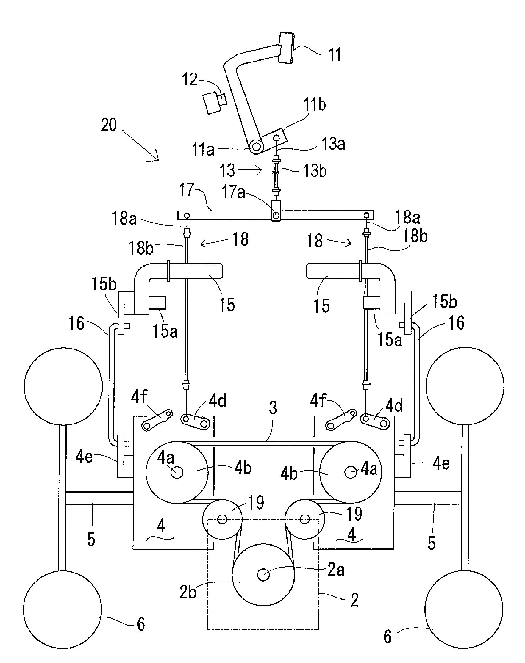
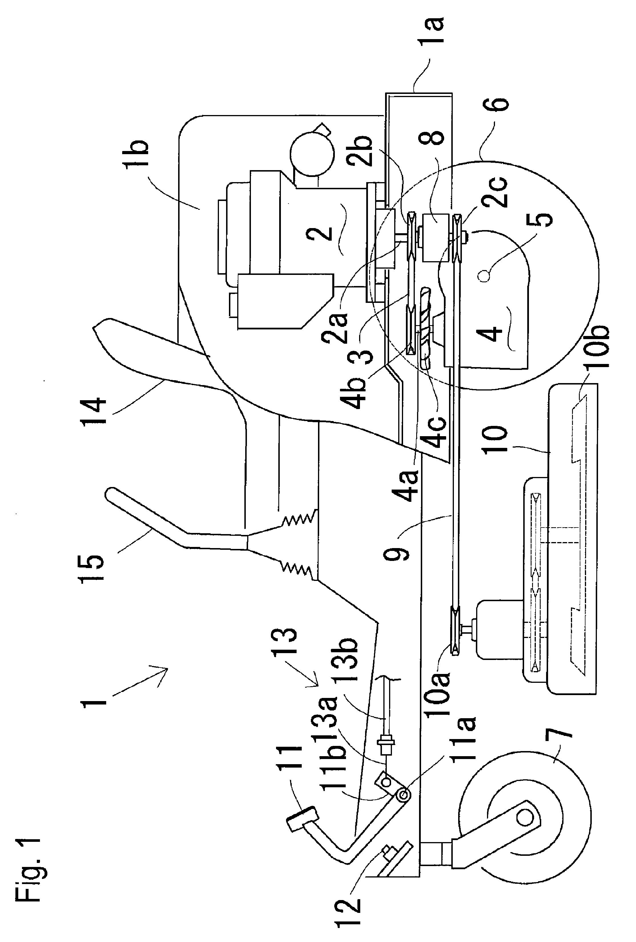
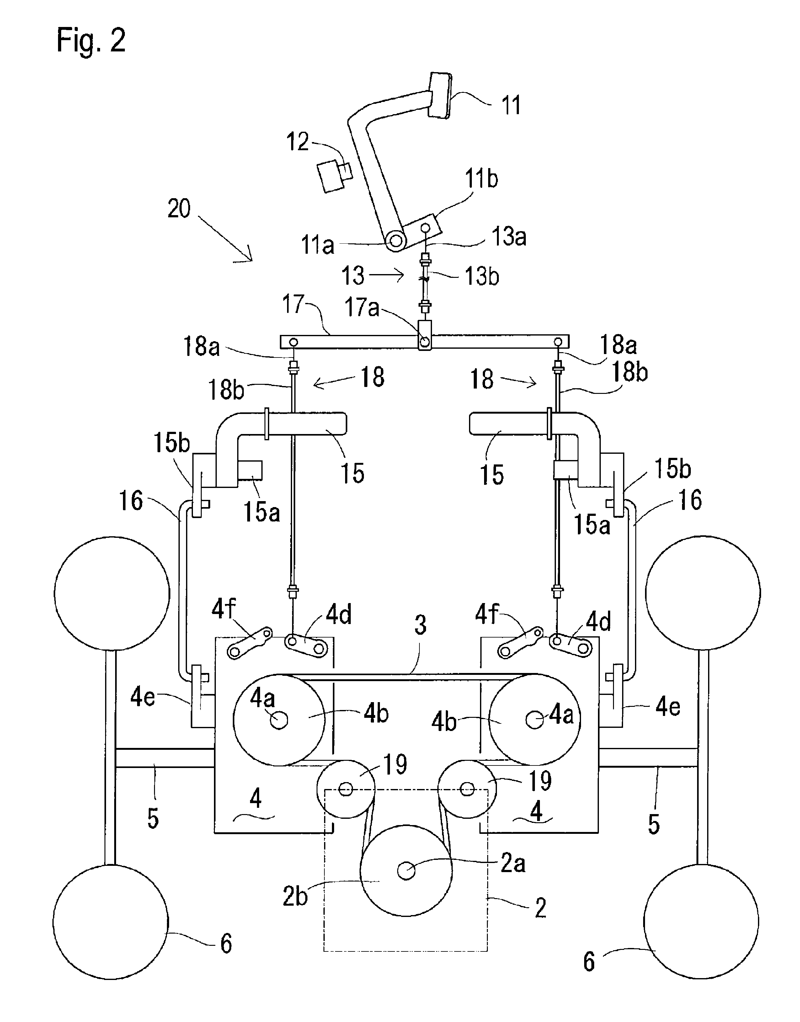
[0030]An entire structure of a zero turn mower 1, serving as an example of zero turn vehicles which can employ the present supplemental brake system, will be described with reference to FIGS. 1 and 2. Hereinafter, zero turn mower 1 is simply referred to as vehicle 1. Vehicle 1 shown in FIG. 1 can employ any of the supplemental brake systems discussed below. However, FIG. 1 illustrates vehicle 1 provided with brake-sensor switch 12 of a representative first supplemental brake system.

[0031]With respect to the upper portion of vehicle 1 above a vehicle body frame 1a, an engine 2 serving as a prime mover is mounted on a rear portion of vehicle body frame 1a, and is covered with a bonnet 1b. An operator's seat 14 is mounted on a front portion of bonnet 1b, and a pair of left and right drive control levers 15 are disposed on left and right sides of seat 14. A brake pedal 11 is disposed just above the front end portion of body frame 1a in front of seat 14.

[0032]With respect to the lower po...


PUM


Abstract

A supplemental brake system of a zero turn vehicle has a prime mover, a brake pedal, a pair of axles, and a pair of transaxles driven by the prime mover so as to drive the respective axles. The transaxles include respective brakes for braking the respective axles according to depression of the brake pedal. Also included are supplemental braking means for stopping transmission of power from the prime mover to the pair of transaxles according to depression of the brake pedal.

Description

BACKGROUND OF THE INVENTION[0001]1. Field of the Invention[0002]The present invention relates to a supplemental brake system of a zero turn vehicle, such as a mower, having a pair of drive wheels and a pair of left and right drive units, such as hydraulic motors, for driving the respective drive wheels.[0003]2. Related Art[0004]As disclosed in Japanese Utility Model No. 2540265, there is a well-known, conventional vehicle brake system for evenly applying braking forces to left and right wheels in response to the depression of a single brake pedal. This conventional brake-equalizing system is especially convenient for a zero turn vehicle, such as a zero turn mower, that is equipped with a pair of left and right transaxles for driving the respective wheels. Because each transaxle includes its own brake, the conventional system allows both brakes to be connected to the common brake pedal.[0005]However, because a zero turn vehicle is equipped with a pair of drive operation devices (such...

Claims


Application Information

Patent Timeline
Patent Type & Authority Patents(United States)
IPC IPC(8): B60T13/74
CPCA01D69/10B60T11/21B60T1/062
Inventor WIEBER, DONALDIRIKURA, KOJIIIDA, MASARU
Owner KANZAKI KOKYUKOKI MFG
Why Eureka
Try Eureka