Illuminating device for liquid crystal panel

a technology of illumination device and liquid crystal panel, which is applied in the direction of lighting and heating apparatus, instruments, display means, etc., can solve the problems of image quality degradation, increased power consumption of display device with liquid crystal panel and illumination device, so as to reduce the number of discharge lamps, reduce uneven brightness, and prevent an increase in thickness

Inactive Publication Date: 2011-06-07
MATSUSHITA ELECTRIC WORKS LTD
View PDF9 Cites 4 Cited by
  • Summary
  • Abstract
  • Description
  • Claims
  • Application Information

AI Technical Summary

Benefits of technology

[0005]In view of the above problem, the object of the present invention is to provide an illuminating device for a liquid crystal panel capable of reducing unevenness in brightness while preventing an increase of the thickness in an anteroposterior direction and reducing the number of the discharge lamps at the same time.
[0007]In the present invention, since the pseudo light source is formed by the light collected near the connection point between the adjacent reflecting surfaces out of the light emitted from the discharge lamps, it is possible to increase the brightness between the adjacent discharge lamps and to reduce the unevenness in brightness. Furthermore, since the plurality of reflecting surfaces are connected to each other on a side nearer to the diffuser plate than the discharge lamps between adjacent two discharge lamps (in other words, each discharge lamp is housed inside the reflecting surface), it is possible to reduce the distance between the reflecting plate and the diffuser plate, as compared with the prior art, and to suppress the thickness dimension in the anteroposterior direction.

Problems solved by technology

However, if the number of the discharge lamps is increased, power consumption of the illuminating device is also increased, and, as a result, power consumption of the display device with a liquid crystal panel and a illuminating device, and the TV receiver are also increased.
Meanwhile, although it is necessary to reduce the number of the discharge lamps which are used so as to reduce the power consumption of the illuminating device for a liquid crystal panel, if the number of the discharge lamps is simply reduced, unevenness in brightness becomes large, whereby image quality is degraded.
As a result, there is a problem that a thickness of the illuminating device is increased.

Method used


Image

  • Illuminating device for liquid crystal panel
  • Illuminating device for liquid crystal panel
  • Illuminating device for liquid crystal panel

Examples


Embodiment Construction

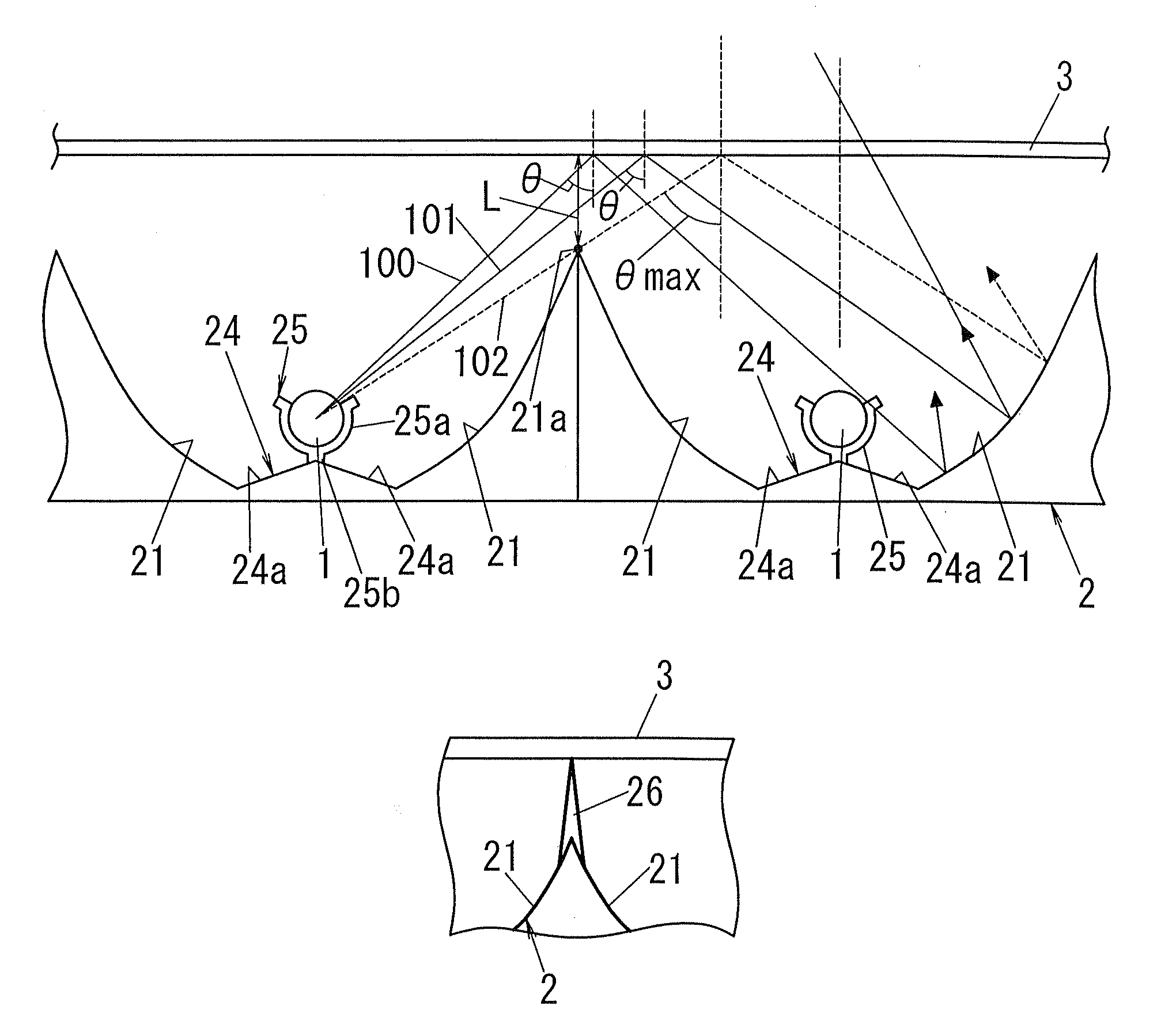
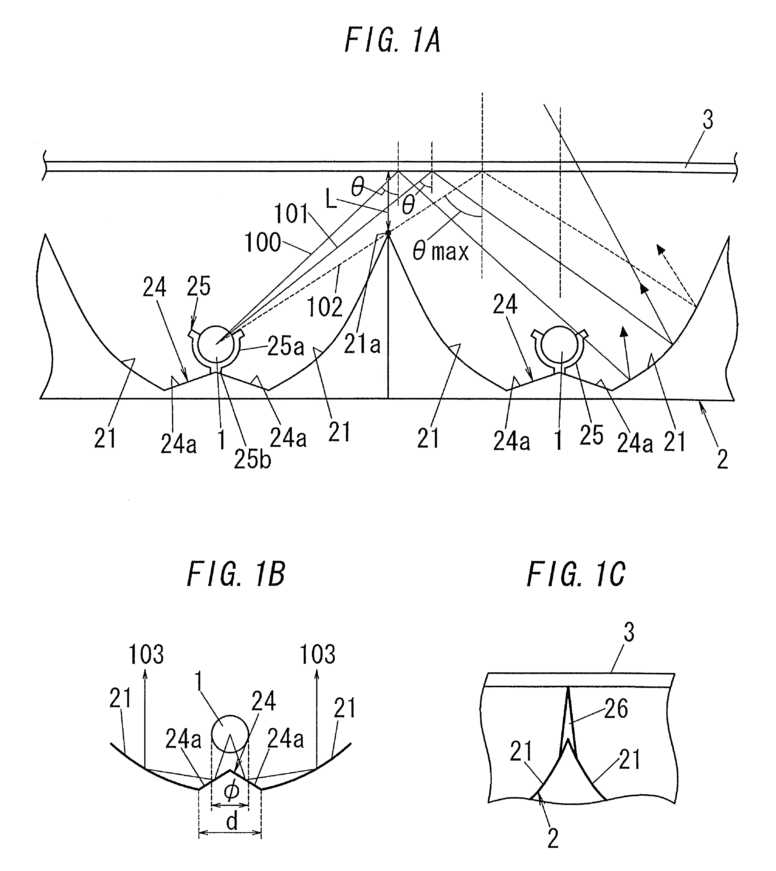
[0022]As shown in FIGS. 3 to 6, the illuminating device of this embodiment includes: a plurality of (twelve in this embodiment) straight-tube type discharge lamps 1 arranged roughly parallel to a back surface of the liquid crystal panel, a reflecting plate 2 disposed behind the discharge lamps 1 to reflect light emitted from the discharge lamps 1 forward (upward in FIG. 3), a plate-shaped diffuser plate 3 disposed between the liquid crystal panel and the discharge lamps 1 to diffuse incident light, a lighting device (not shown) for supplying power to the discharge lamps 1 (electrodes of the discharge lamps) through terminal pins 1a provided at both ends of each discharge lamp 1 to illuminate the discharge lamp, two circuit substrates 4 on which at least a part of the circuit parts for constituting the lighting device is mounted on and which are disposed on the back side of the reflecting plate 2, a diffuser sheet 5 disposed in front of the diffuser plate 3, a lens sheet 6 disposed i...


PUM


Abstract

Light which tries to enter a diffuser plate 3 at an angle which exceeds an angle at which a percentage of reflected light increases rapidly (that is, the incidence angle θ=70 degrees) is all reflected by a reflecting surface 21 and then enters the diffuser plate 3. Therefore, a pseudo light source is formed by light which was collected near a connection point between adjacent reflecting surfaces 21 out of the emitted light of the discharge lamps 1. So, the brightness between the adjacent discharge lamps 1 is increased, and it is possible to reduce unevenness in brightness. Furthermore, since the discharge lamp 1 is housed inside the reflecting surface 21 whose cross-sectional shape is a parabola, it is possible to reduce the distance between a reflecting plate 2 and the diffuser plate 3, as compared with the prior art, and to reduce the thickness dimension in the anteroposterior direction.

Description

TECHNICAL FIELD[0001]The present invention relates to an illuminating device for a liquid crystal panel which illuminates a transmissive liquid crystal panel from behind.BACKGROUND ART[0002]In recent years, a big-screen display device and a TV receiver which use a transmissive liquid crystal panel have spread rapidly. The transmissive liquid crystal panel needs an illuminating device (so-called backlight) which illuminates the transmissive liquid crystal panel from behind. With upsizing of the liquid crystal panel, the illuminating devices are also getting larger, and the number of the light sources (straight-tube type discharge lamps) used have continued to rise. However, if the number of the discharge lamps is increased, power consumption of the illuminating device is also increased, and, as a result, power consumption of the display device with a liquid crystal panel and a illuminating device, and the TV receiver are also increased. Meanwhile, although it is necessary to reduce t...

Claims


Application Information

Patent Timeline
Patent Type & Authority Patents(United States)
IPC IPC(8): G09F13/04
CPCG02F1/133604G02F1/133605G02F1/133611
Inventor MATSUKAWA, KAZUYUKIKAMADA, MASAOTANAKA, WATARUWATANABE, KAZUKINARA, ISAOUEMOTO, YASUO
Owner MATSUSHITA ELECTRIC WORKS LTD
Why Eureka
Try Eureka