
Dental prophylaxis angle and handpiece assembly

a technology for prophylaxis angles and handpieces, applied in dental surgery, dental cleaning, medical science, etc., can solve the problems of difficult removal of broken off drive shafts from handpieces, poor stability of prophylaxis angles when mounted on handpieces, etc., and achieve the effect of better grip and feel

Active Publication Date: 2011-06-07
DENTSPLY SIRONA INC
View PDF109 Cites 18 Cited by
  • Summary
  • Abstract
  • Description
  • Claims
  • Application Information

AI Technical Summary

Benefits of technology

"The present invention is a dental handpiece and prophy angle assembly used for cleaning and polishing teeth. The prophy angle is removably attached to the handpiece and includes an elongated tubular body with proximal and distal end portions. The distal end of the drive shaft has a piloting tip for guiding the prophy angle onto the dental handpiece. The dental handpiece includes a forward-facing tubular nose portion and a rear-facing handle portion. The nose portion includes a central aperture for receiving the piloting tip and a locking annular member for engaging the first and second locking tabs of the prophy angle. The dental handpiece and prophy angle are assembled together using interlocking drive members and complementary-shaped cut-out portions or locking recessions. The technical effects of this invention include improved cleaning and polishing efficiency, ease of use, and better grip and feel."

Problems solved by technology

For example, after prolonged use and excessive vibrational motion, some drive shafts of some prophy angles can shear off in the handpiece.
The broken-off drive shaft can be difficult to remove from the handpiece and normally it must be returned to the factory for repair.
Another problem with some conventional prophy angle and handpiece systems is that the prophy angle shows poor stability when it is mounted on the handpiece.
Some prophy angles tend to wobble and rock.
This can cause significant problems when the prophy angle / handpiece assembly is being used during a cleaning procedure.
A dental professional may feel uncomfortable using such an unstable prophy angle / handpiece assembly, and it may cause added anxiety for the user and patient being treated.

Method used


Image

  • Dental prophylaxis angle and handpiece assembly
  • Dental prophylaxis angle and handpiece assembly
  • Dental prophylaxis angle and handpiece assembly

Examples


Embodiment Construction

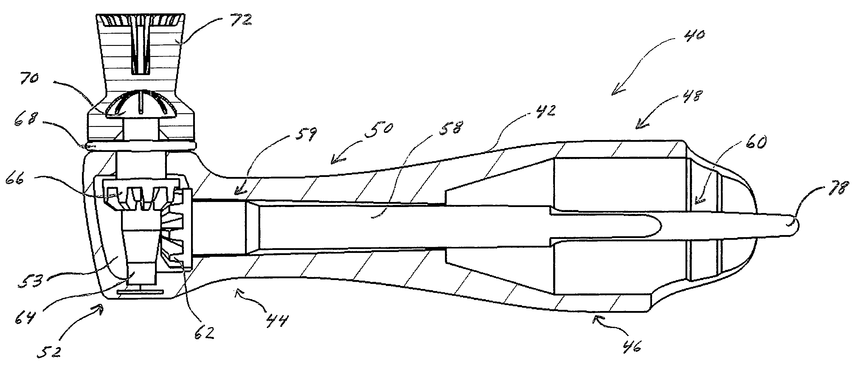
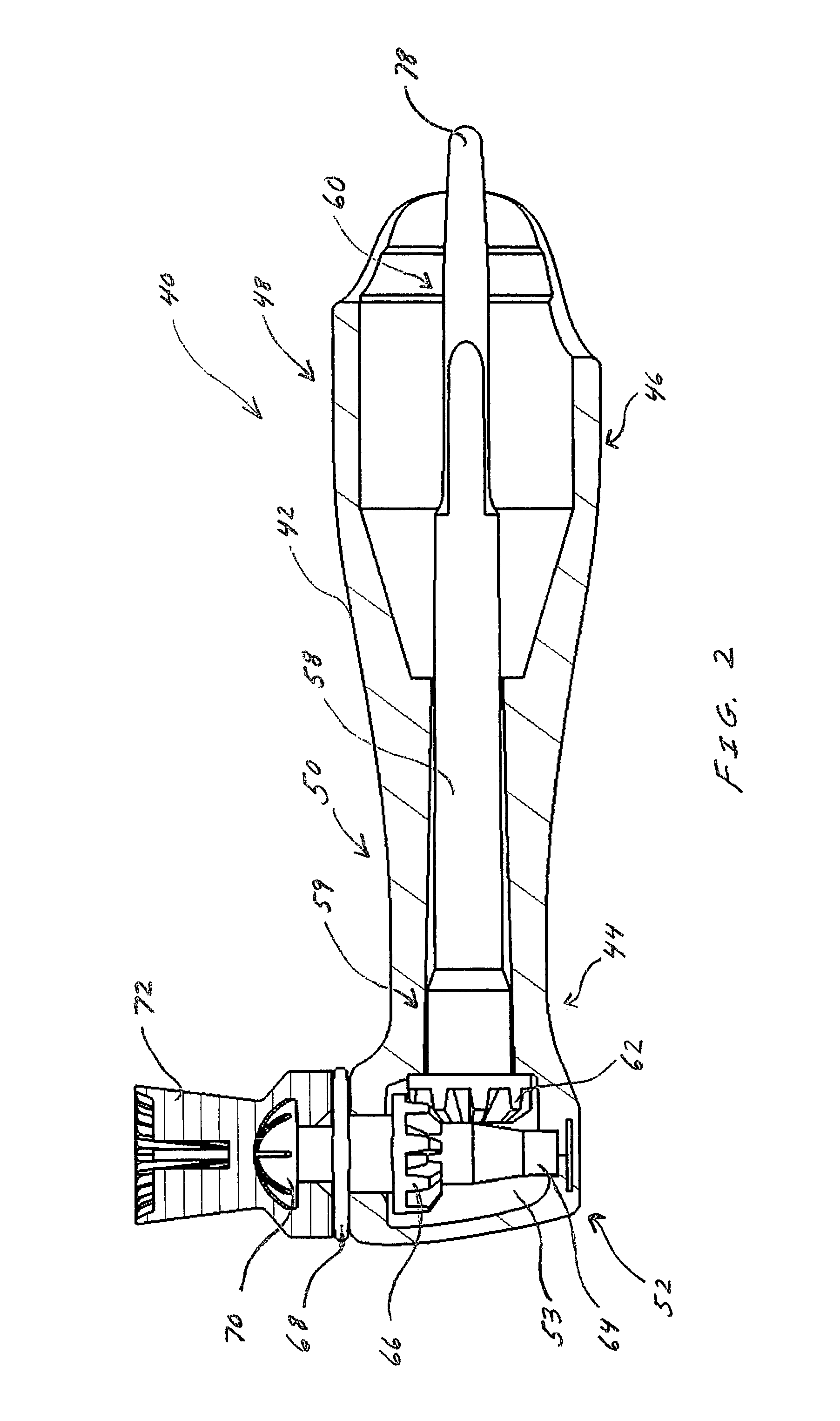
[0036]Referring to the drawings, the prophy angle of the instant invention is generally indicated at (40) in FIG. 2. As will be hereinafter more fully described, the prophy angle (40) generally comprises an elongated tubular body (42) with proximal (44) and distal (46) end portions. The tubular body (42) includes a handle or sleeve region (48), a neck region (50), and a head region (52) that defines a hollow chamber (53). The interior of the tubular body (42) defines a central bore extending from the proximal (44) to distal (46) end portions. The bore in the handle (48) has substantially the same diameter as the diameter of the dental handpiece (not shown) that will receive the prophy angle (40). The diameter of the bore tapers off so that the neck region (50) has a smaller diameter than the handle (48). The distal end (46) of the tubular body (42) includes a first locking extension (54) with a first locking tab (55) and an opposing second locking extension (56) with a second lockin...


PUM

PropertyMeasurementUnit
prophy angleaaaaaaaaaa
angleaaaaaaaaaa

Abstract

A dental prophylaxis angle and handpiece assembly for cleaning and polishing teeth is provided. The dental prophylaxis angle is removably attached to the dental handpiece by an interlocking mechanism that includes extension locking tabs, a locking annular member, and an interlocking drive member in the handpiece. The prophy angle is securely snap-fitted onto the handpiece and locked in place so that it has minimal lateral movement. After the prophy angle has been used to treat a patient, it can be removed easily from the handpiece and disposed thereof.

Description

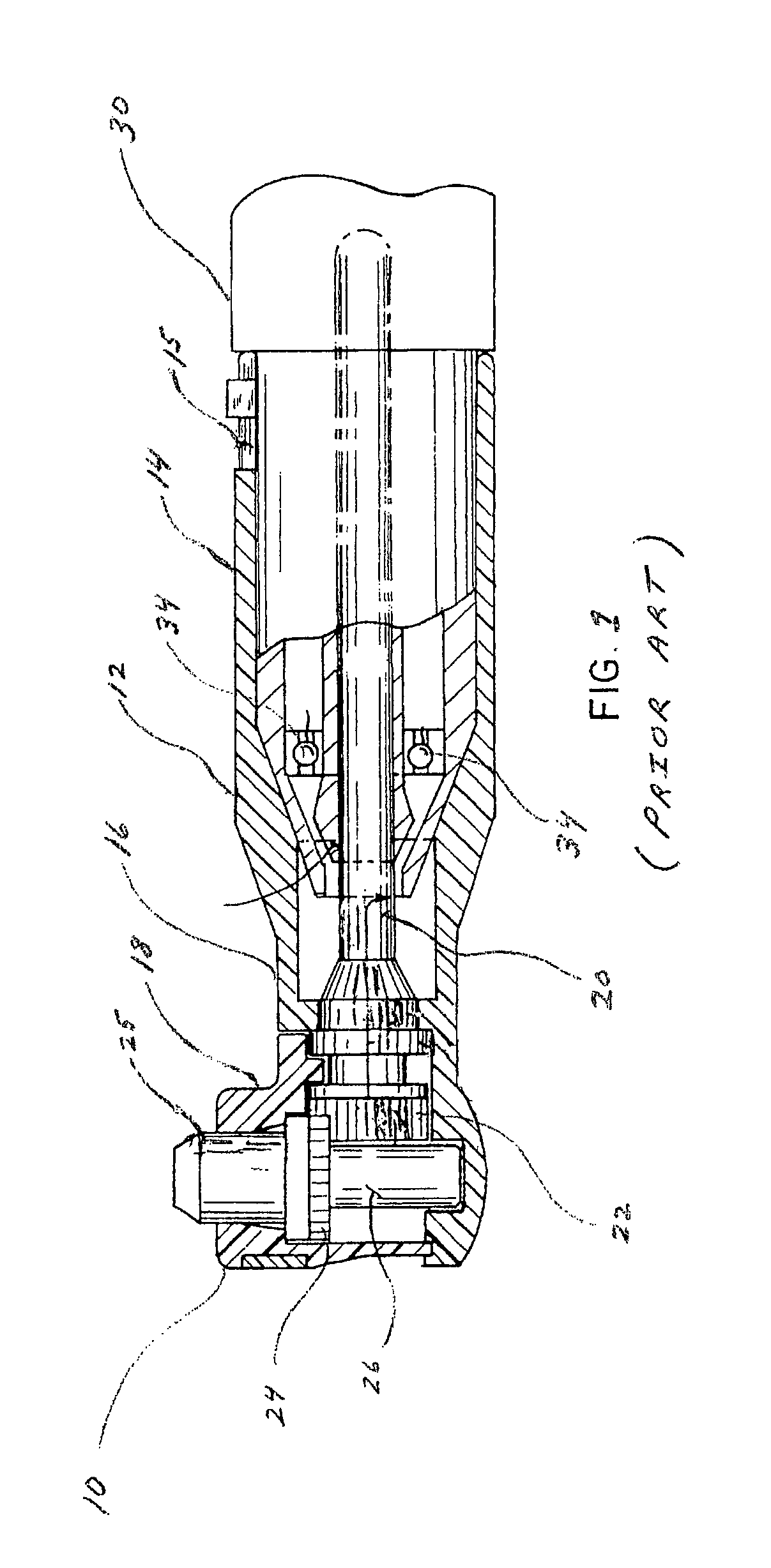
BACKGROUND OF THE INVENTION[0001]1. Field of the Invention[0002]The present invention relates generally to dental instruments used for cleaning and polishing teeth. More particularly, the invention relates to a dental prophylaxis angle and handpiece assembly. The dental prophylaxis angle is removably attached to the dental handpiece by a new interlocking mechanism.[0003]2. Brief Description of the Related Art[0004]Today, dental professionals use dental instruments commonly known as dental prophylaxis (prophy) angles for cleaning and polishing teeth. Referring to FIG. 1, traditional prophy angles (10) include a one-piece or multi-piece tubular housing (12) having sleeve (14), neck (16), and head (18) portions. Normally, the head portion (18) extends at an angle of ninety (90) degrees with respect to the neck portion (16). However, in some cases, contra-prophy angles having a head portion that extends at an angle of greater than 90 degrees are used. Dental professionals use the contra...

Claims


Application Information

Patent Timeline
Patent Type & Authority Patents(United States)
IPC IPC(8): A61C3/06
CPCA61C17/005A61C1/185Y10T29/4973
Inventor CHRONISTER, BENJAMINKILE, JEREMYWERNER, PETERBEANE, BRETHEIL, DONALDSHERMAN, JAMESWHITCOMB, ROBERT
Owner DENTSPLY SIRONA INC
Learn More