
Electrosurgical instrument and method of use

a technology of electrosurgical instruments and jaws, applied in the field of electrosurgical jaw structures, can solve the problems of non-uniform denatured tissue not creating a seal with significant strength, and achieve the effects of uniform thermal effect, high localization, and rapid on-off switching of current flow

Active Publication Date: 2011-06-07
ETHICON ENDO SURGERY INC
View PDF256 Cites 363 Cited by
  • Summary
  • Abstract
  • Description
  • Claims
  • Application Information

AI Technical Summary

Benefits of technology

[0011]In another aspect, embodiments of the invention provide system and methods for uniformly heating and welding tissue using the application of Rf energy. In order to create the most effective “weld” in tissue, a targeted volume of tissue is desirably uniformly elevated to the temperature needed to denature proteins therein. To create a “weld” in tissue, collagen, elastin and other protein molecules within an engaged tissue volume are desirably denatured by breaking the inter- and intra-molecular hydrogen bonds—followed by re-crosslinking on thermal relaxation to create a fused-together tissue mass. It can be easily understood that ohmic heating in tissue—if not uniform—can at best create localized spots of truly “welded” tissue. Such a non-uniformly denatured tissue volume still is “coagulated” and will prevent blood flow in small vasculature that contains little pressure. However, such non-uniformly denatured tissue will not create a seal with significant strength (e.g. burst or leak strength, etc), for example in 2 mm. to 10 mm. arteries that contain high pressures. Accordingly, embodiments of the invention utilize positive temperature coefficient of resistance and related materials to sense and respond to temperature in engaged tissue to modulate Rf energy delivery to the engaged tissue to uniformly heat a target tissue volume to in turn produce a uniformly denatured tissue volume and thus, a uniformly welded tissue volume.
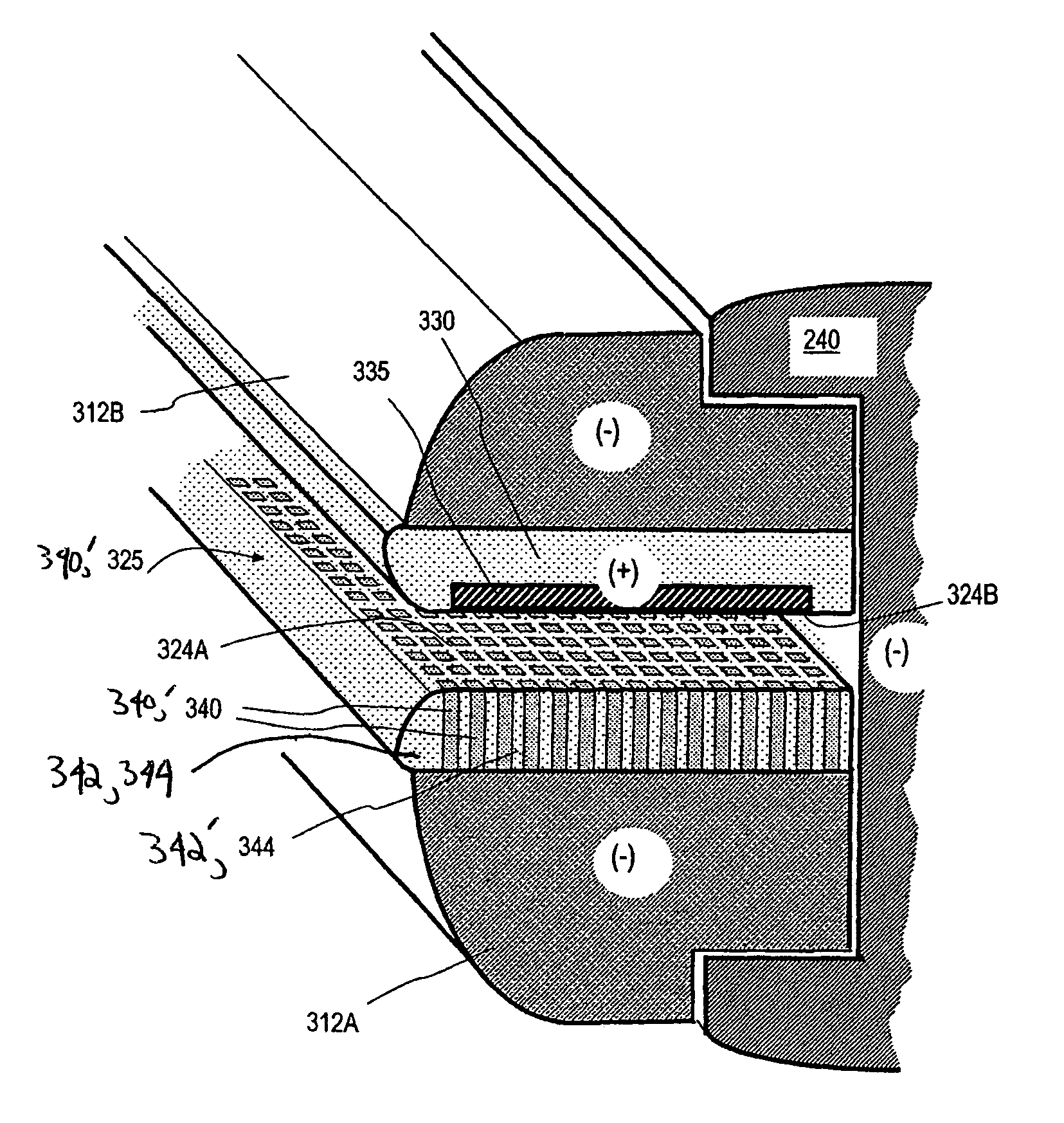
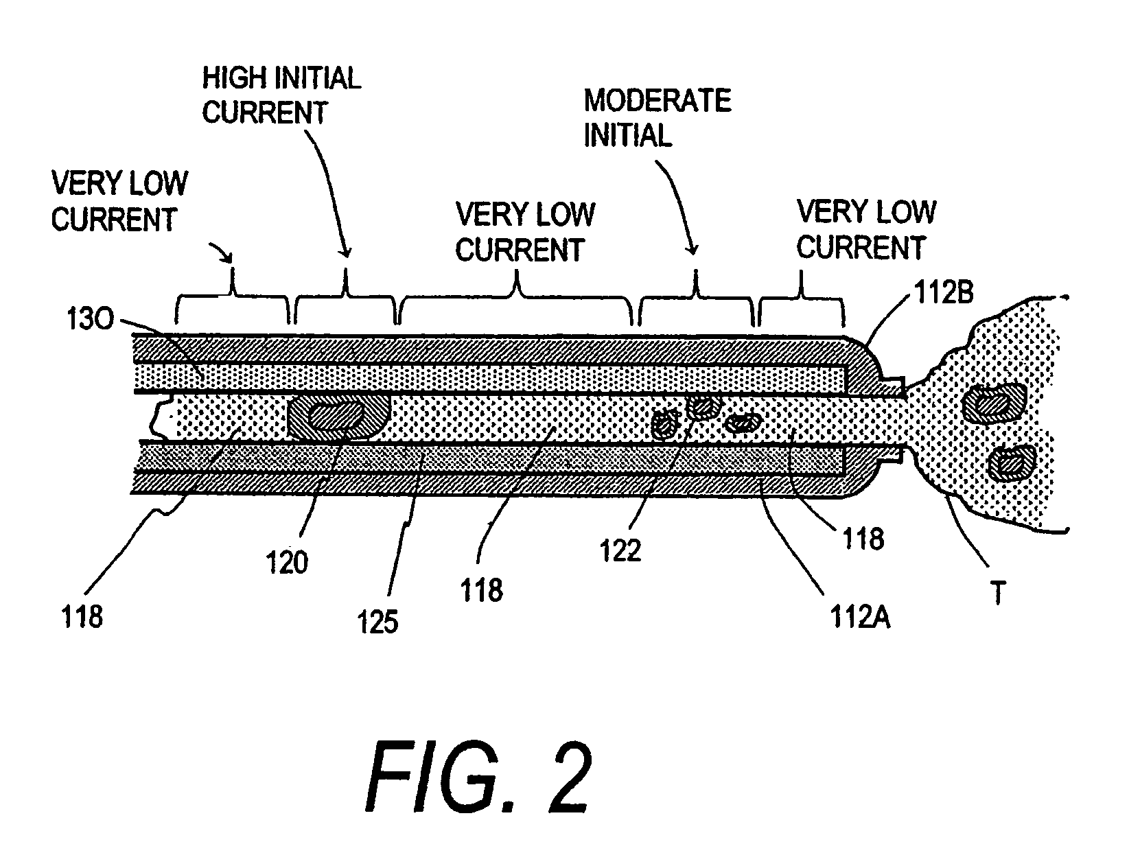
[0015]In many embodiments, the PTCR body can comprises a matrix comprising PTCR pixels disposed in a field material (i.e., a non pixilated material) such as an electrically insulative polymer material. The jaw structure can be configured to use the PTCR pixels for one or more of the following: i) performing highly localized, pixelated temperature sensing of ohmically heated tissue; ii) controlling current flow in engaged tissue on a highly localized pixelated basis; iii) producing rapid on-off switching of current flow to engaged tissue on a highly localized pixelated basis; and iii) producing highly localized, pixelated Rf current densities in engaged tissue. In various embodiments, the pixel portions can comprise an array wherein each pixel is independently switchable, responsive to the temperature of tissue adjacent each pixel portion, or another tissue property such as resistance, hydration level etc. Also, the array can be configured to produce a substantially uniform thermal effect in tissue including at least one of tissue welding, tissue weld strength, ohmic heating or protein denaturization.
[0016]A particular embodiment of the invention provides an electrosurgical working end for performing high strength welding of tissue comprising a body having a tissue contacting surface. The body includes pixel portions and non-pixel portions distributed within the tissue contacting surface. The pixel portions comprise a positive temperature coefficient of resistance (PTCR) material with at least one pixel portion configured to switch Rf current on and off in the at least one pixel portion responsive to tissue temperature adjacent the at least one pixel portion. The pixel portions can be configured to be coupled to an Rf current source such as an Rf generator known in the art. The Rf current source can be coupled to an interior of the body, for example, by doping the body with a conductive coating. Also, the shape of the pixels can be configured to achieve selectable thermal, electrical and / or mechanical properties or a combination properties for the body (e.g. faster pixel switching times, more precise spatial control, etc.)
[0017]In an exemplary method of using the above embodiment of the working end and related embodiments, tissue is engaged with the tissue contacting surface of the working end and Rf energy is then delivered to tissue to ohmically heat tissue. Rf current flow to tissue through at least one pixel portion can then be switched or toggled off or one responsive to the temperature of ohmically heated tissue adjacent the at least one pixel portion. This switching can be done on a micron scale so that current flows in one pixel, but is switched off in an adjacent pixel only microns away. On a more macro scale, the switching of current flow can also be utilized to produce a substantially uniform thermal effect in a tissue volume engaged with the tissue contacting surface. This thermal effect can include without limitation, uniform tissue welding, tissue weld strength, ohmic heating, uniform protein denaturization, uniform. Additionally, the switching of current flow can be utilized to create regionalized or pixilated current densities in the engaged tissue which can correlate to the pixel portions.
[0018]In some embodiments, the non-pixel portion can have a different or lesser mechanical compressibility than the pixel portions so as to facilitate the gripping or engagement of tissue during the application of force and energy by the working end. The difference in compressibility allows for recesses in the non-pixel portions of the surface to grip the tissue as well as allowing for portions of the surface to dynamically change shape in response to physical changes in the engaged tissue (e.g., shrinkages) as the tissue is heated. This difference in compressibility can also be utilized to maintain minimum hydration levels in tissue during Rf energy delivery by capturing migrating tissue fluid in recesses of the non-pixel portions and hydrating engaged tissue during the delivery of Rf energy using the captured fluid.

Problems solved by technology

However, such non-uniformly denatured tissue will not create a seal with significant strength (e.g. burst or leak strength, etc), for example in 2 mm. to 10 mm. arteries that contain high pressures.
Such surface coagulation does not create a weld that provides any substantial strength in the affected tissue.

Method used


Image

  • Electrosurgical instrument and method of use
  • Electrosurgical instrument and method of use
  • Electrosurgical instrument and method of use

Examples


Embodiment Construction

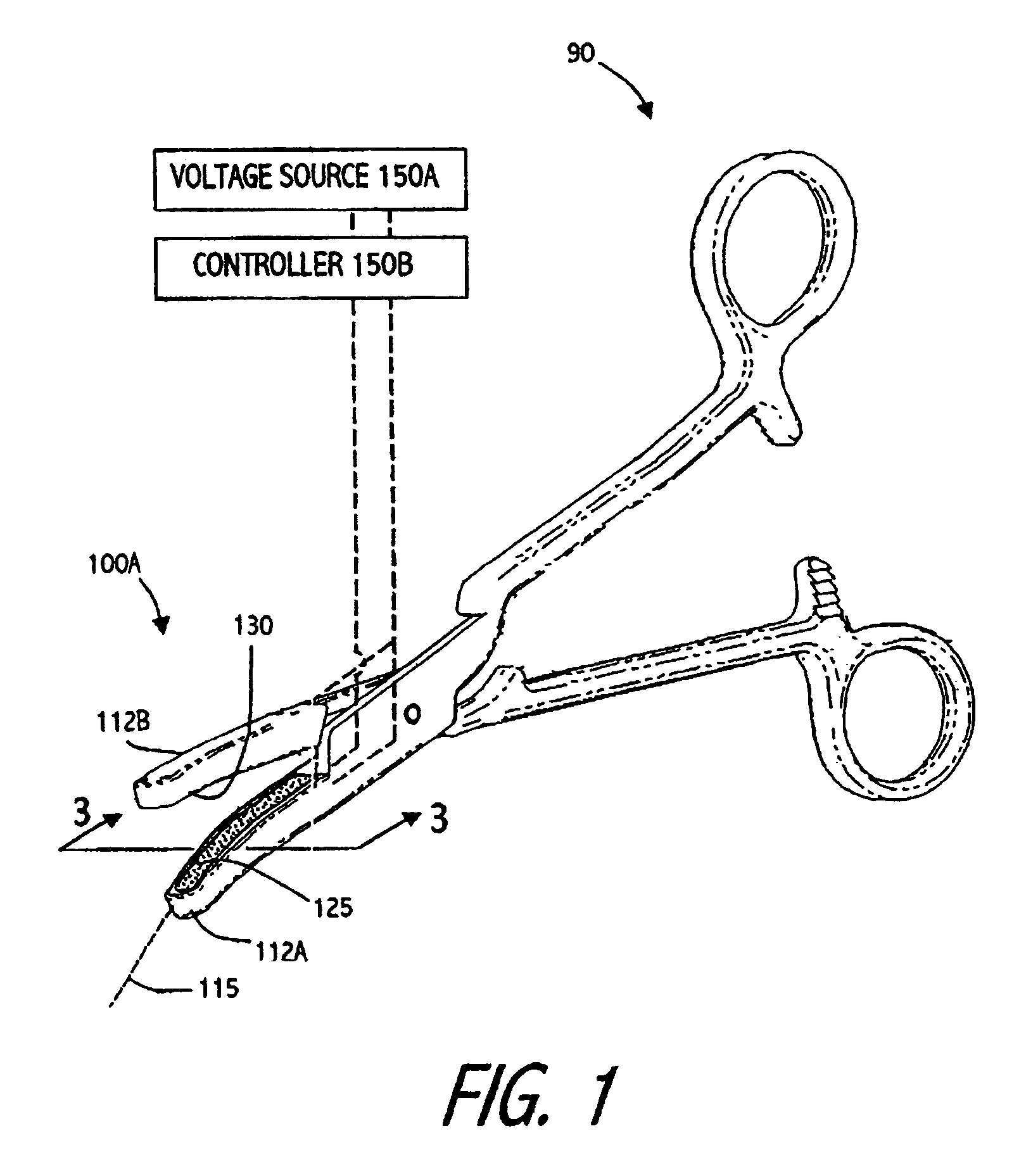
[0051]1. Electrosurgical jaw structure with variable resistive matrices. Various embodiments of the invention provide systems and methods to deliver energy to targeted tissue volumes in a controlled manner to thermally weld or seal targeted tissue. Particular embodiments provide systems and methods for contemporaneously (i) engaging tissue between paired jaws, (ii) delivering energy to the tissue, and (iii) optionally transecting the tissue to provide a “one-step” welding-transecting procedure. Many embodiments provide a jaw structure configured to engage and weld tissue bundles, that is bundles of disparate tissue types (e.g., fat, blood vessels, fascia, etc.). For the welding of tissue bundles, the jaw surfaces can be configured to apply differential energy levels to each different tissue type simultaneously. Related aspects of the invention provide an electrosurgical system that can apply differential energy levels across the jaws engagement surfaces with “smart” materials withou...


PUM


Abstract

A particular embodiment of the invention provides an electrosurgical working end for performing high strength welding of tissue comprising a body having a tissue contacting energy delivery surface. The body includes pixel portions and non-pixel portions distributed within the tissue contacting surface. The pixel portions comprise a positive temperature coefficient of resistance (PTCR) material with at least one pixel portion configured to switch Rf current on and off in the at least one pixel portion responsive to tissue temperature adjacent the at least one pixel portion. The pixel portions can be configured to be coupled to an Rf current source such as an Rf generator. The pixelated energy delivery surfaces are capable of highly localized modulation of Rf energy application to the engaged tissue to create high strength tissue welds.

Description

CROSS-REFERENCES TO RELATED APPLICATIONS[0001]This applications claims the benefit of priority of U.S. Provisional Application No. 60 / 552,978, filed on Mar. 12, 2004, the full disclosure of which is incorporated herein by reference. This application is also related to U.S. patent application Ser. No. 10 / 032,867 filed Oct. 22, 2001 now U.S. Pat. No. 6,929,644, titled Electrosurgical Jaws Structure for Controlled Energy Delivery, U.S. patent application Ser. No. 10 / 351,449 filed Jan. 22, 2003 now U.S. Pat. No. 7,112,201, titled Electrosurgical Instrument and Method of Use, U.S. patent application Ser. No. 10 / 443,974, filed May 22, 2003 now U.S. Pat. No. 7,041,102, titled Electrosurgical Working End with Replaceable Cartridges, and Provisional U.S. Patent Application Ser. No. 60 / 523,567, filed Nov. 19, 2003 titled Electrosurgical Instrument and Method of Use, all of which are fully incorporated herein by reference.BACKGROUND OF THE INVENTIONField of the Invention[0002]Embodiments of th...

Claims


Application Information

Patent Timeline
Patent Type & Authority Patents(United States)
IPC IPC(8): A61B18/14
CPCA61B18/1442
Inventor TRUCKAI, CSABASHADDUCK, JOHN H.
Owner ETHICON ENDO SURGERY INC
Learn More