External fixation system

a fixation system and external technology, applied in the field of external fixation system, can solve the problems of disorientation fracture, cumbersome use of different wire clamps, and inability to stabilize force at the intersection,

Active Publication Date: 2011-06-07
STRYKER EURO OPERATIONS HLDG LLC
View PDF10 Cites 57 Cited by
  • Summary
  • Abstract
  • Description
  • Claims
  • Application Information

AI Technical Summary

Benefits of technology

[0005]One aspect of the present invention is to provide an external orthopedic fixation ring for use with an external fixator that overcomes the disadvantages of prior art fixation rings. In particular the fixation ring shall be shaped to allow a simple placement of wires or pins in different planes or levels.
[0007]The first, second and third surfaces provide three parallel and displaced planes in each of which a wire can be arranged. This is particularly advantageous as the wires cross themselves in different planes. This prevents a bending of the wires in the vicinity of the crossing point.

Problems solved by technology

Upon tensioning of this distorted wire, an unstable force occurs at the intersection.
This instability leads to bone movements and can disorient the fracture.
The use of different wire clamps is cumbersome and complicated for the medical practitioner as the height of said clamps has to be adjusted for example, to provide the separate parallel planes for each wire.
However, the use of such elements is rather cumbersome and complicated.

Method used


Image

  • External fixation system
  • External fixation system
  • External fixation system

Examples


Embodiment Construction

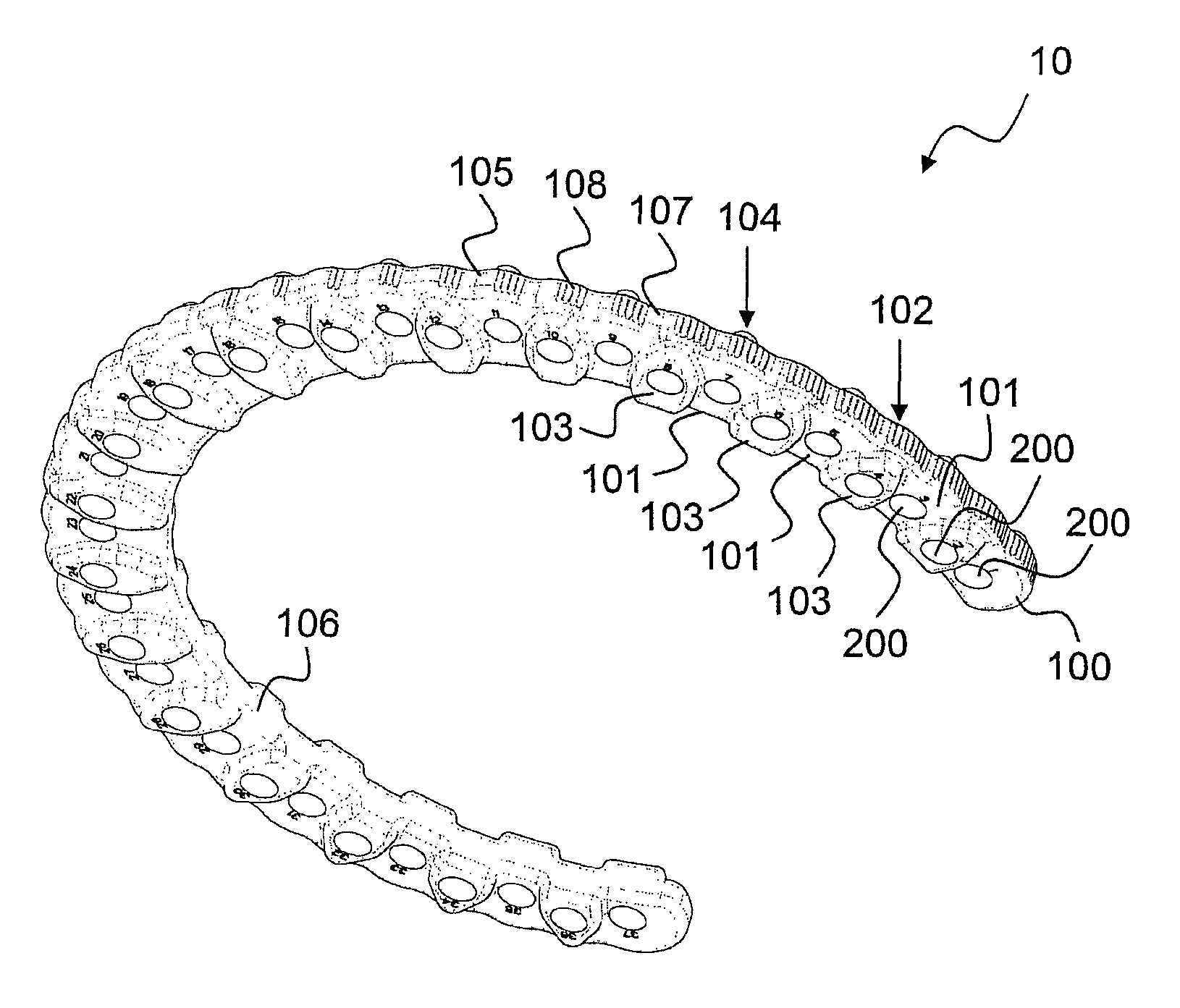
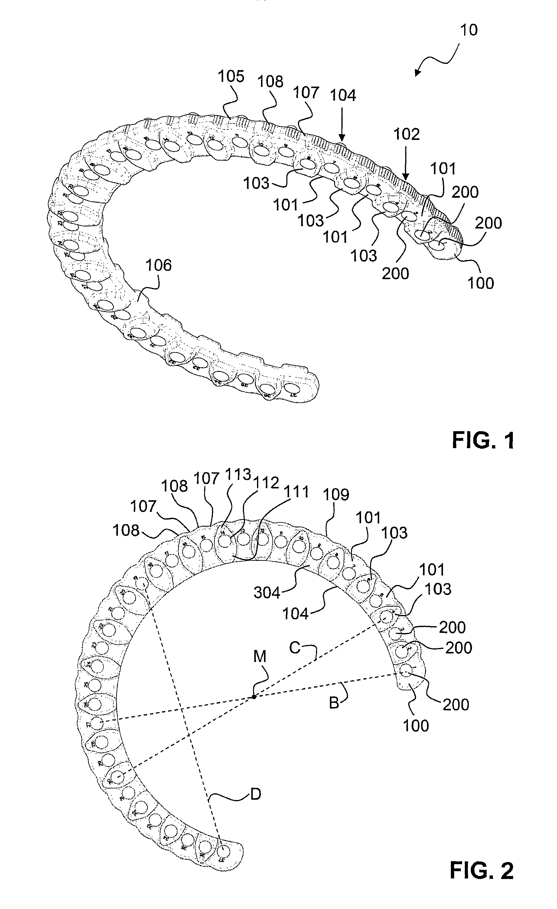
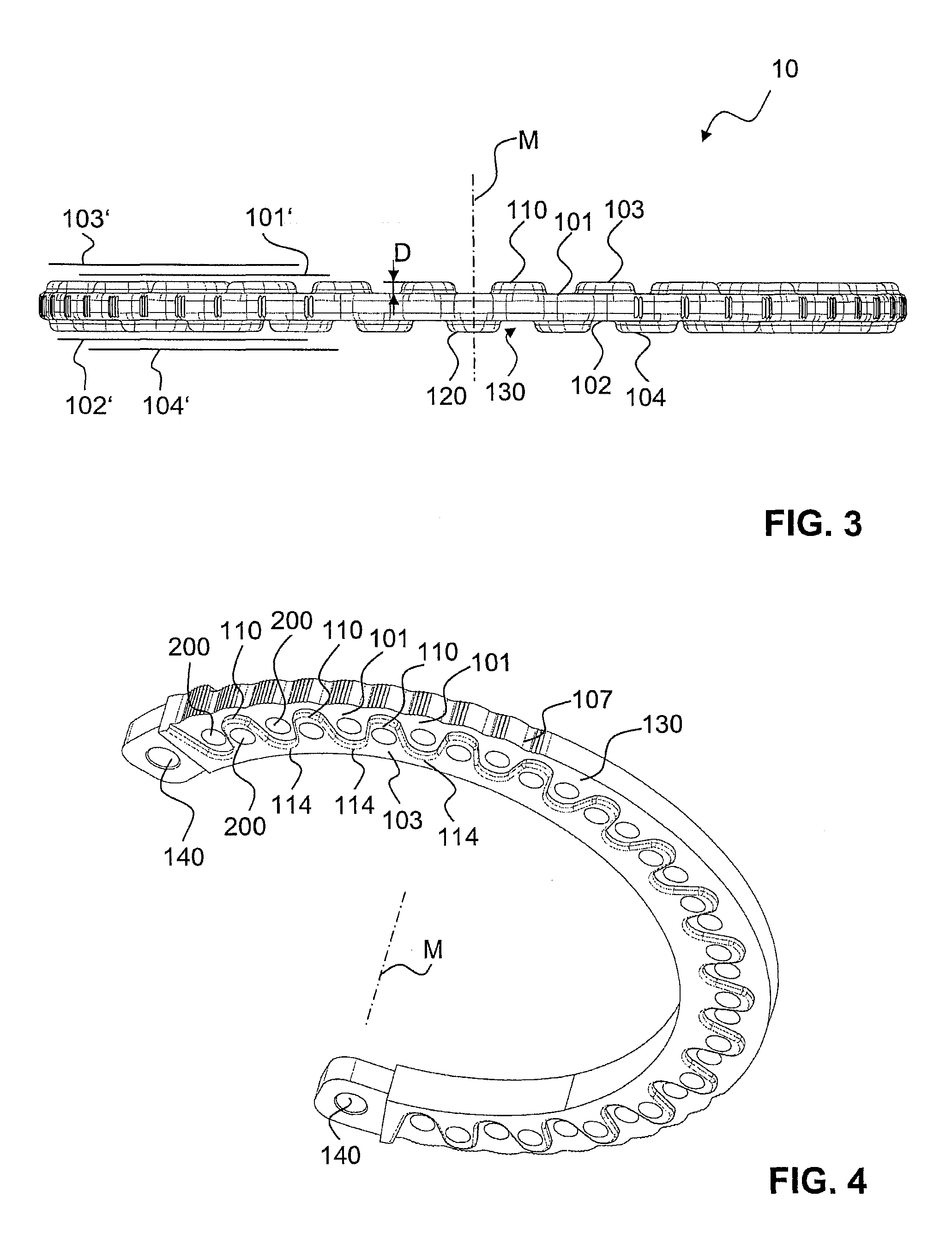
[0032]Referring to FIGS. 1 to 3 there is shown an external fixation system generally denoted as 10 according to a first embodiment of the present invention comprising an open ring segment. The orthopedic fixation plate is used to accommodate clamped elements in order to fixate a wire (e.g. a Kuentscher Wire) or pin that is in an engagement with a bony structure such as a fractured long bone to the ring. In the preferred embodiment the external fixation plate has the shape of a ring segment covering an angle at about 250° to 260°.

[0033]The preferred fixation ring 100 has the shape of a circular ring or of a ring segment having a central axis (M) around which the ring extends. The ring 100 comprises a first surface 101 and a second surface 102. The first surface 101 and the second surface 102 are parallel to each other and both are perpendicular to the central ring (M). The ring is furthermore limited by an outer surface 105 and an inner surface 106.

[0034]The fixation plate 100 compri...


PUM


Abstract

An orthopedic fixation ring for an external fixator has a ring or a ring-segment extending around a center axis. The ring comprises a first surface running perpendicular to the center axis, a second surface which is parallel to the first surface, and a plurality of spaced apart through openings running parallel to the center axis and extending through the fixation plate. The fixation plate has at least a third surface which is parallel to the first surface spaced outwardly thereof with respect to the center axis. A further set of through openings extends from the first surface to the third surface. A fourth surface may be provided which is axially displaced from the second surface with respect to the center axis. The ring preferably is circular or part-circular and is molded from carbon fiber reinforced PEEK.

Description

BACKGROUND OF THE INVENTION[0001]External orthopedic fixation systems having the shape of plates or rings for the use with clamps and bone are known for fracture fixation. The person skilled in the art knows such rings for example from the Illizarov Apparatus. Thereby several rings are positioned around limbs interconnected by struts and used to accommodate elements such as posts etc. which are in connection with a Kirchner wire or pin connected to a bony structure on either side of a fracture. Such rings are commonly used for wire placement or pin placement. Tensioned wires are in an engagement with said bony structure and at two circumferentially spaced positions on a single ring.[0002]U.S. Pat. No. 5,275,598, for example, discloses a ring having several openings that are arranged in regular intervals. Thereby the wires are fixed by means of nuts and bolts with the opening of the ring. Several wires are arranged such that they extend from one side of the ring across the inner ring...

Claims


Application Information

Patent Timeline
Patent Type & Authority Patents(United States)
IPC IPC(8): A61B17/00
CPCA61B17/62
Inventor STEINER, CHRISTIANBURGHERR, VINZENZFIECHTER, MEINRAD
Owner STRYKER EURO OPERATIONS HLDG LLC
Why Eureka
Try Eureka