
Assembly for fixing and connecting light bar lamp

a technology for fixing and connecting light bars, which is applied in the field of lamps, can solve the problems of not being lighted up, unable to adjust the irradiation direction, and the wiring process will spend a lot of time and labor

Inactive Publication Date: 2011-06-14
WIESON TECH CO LTD
View PDF7 Cites 12 Cited by
  • Summary
  • Abstract
  • Description
  • Claims
  • Application Information

AI Technical Summary

Benefits of technology

Enables flexible adjustment of the irradiation direction of LED light bar lamps and facilitates easy connection and disconnection of multiple lamps in series, reducing installation time and maintenance complexity while ensuring reliable electrical contact.

Problems solved by technology

When the elongated lamp seats are fixed to the wall or the inner wall of an exhibition cabinet, since the LED light bar lamps can emit light in one direction only, it is impossible to adjust the irradiating direction.
However, the wiring process will spend a lot of time and labor.
Further, if any one wire fails to generate a good or correct electrical contact, the related LED light bar lamps will not be lighted up.
Alternatively, when the LED light bar lamps are damaged, it is not easy to detach and repair the damaged LED light bar lamps or re-connect the wires, causing the troubles in repair and maintenance.

Method used


Image

  • Assembly for fixing and connecting light bar lamp
  • Assembly for fixing and connecting light bar lamp
  • Assembly for fixing and connecting light bar lamp

Examples


Embodiment Construction

[0022]The technical contents and detailed description of the present invention will be explained with reference to the accompanying drawings.

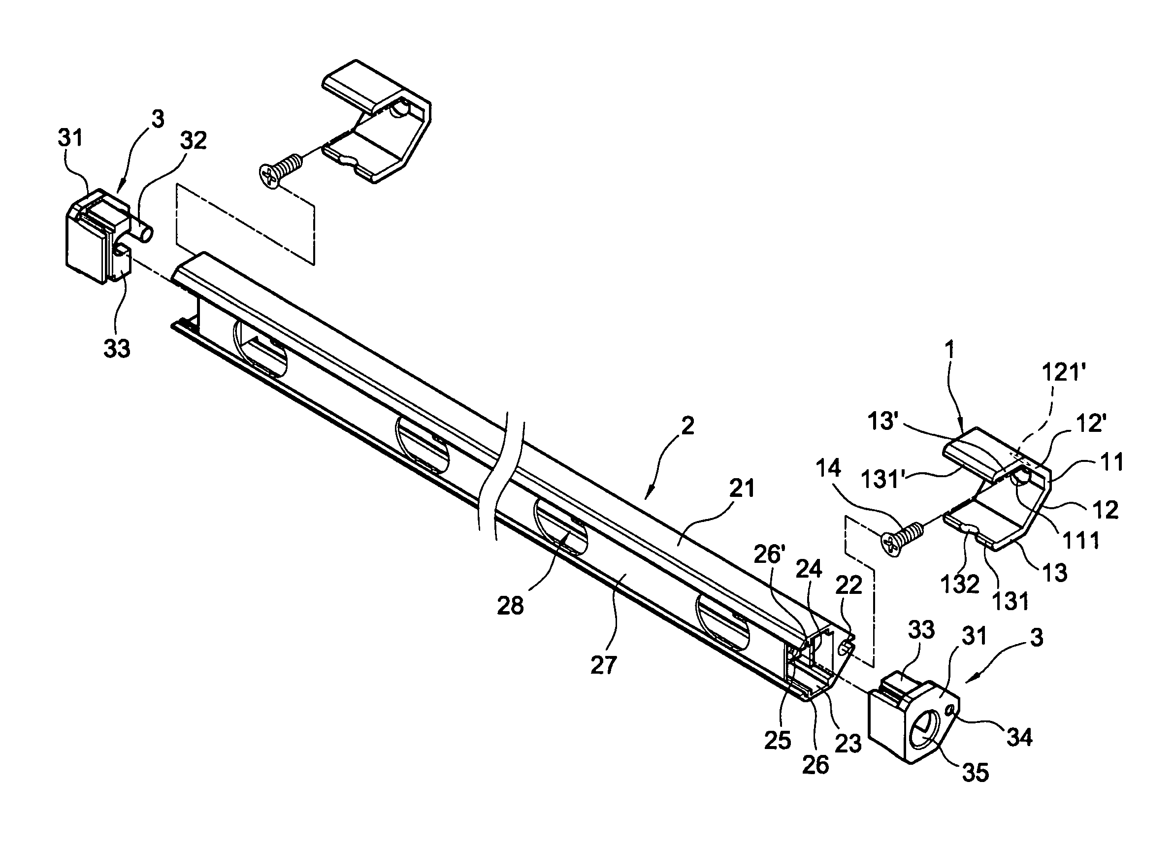
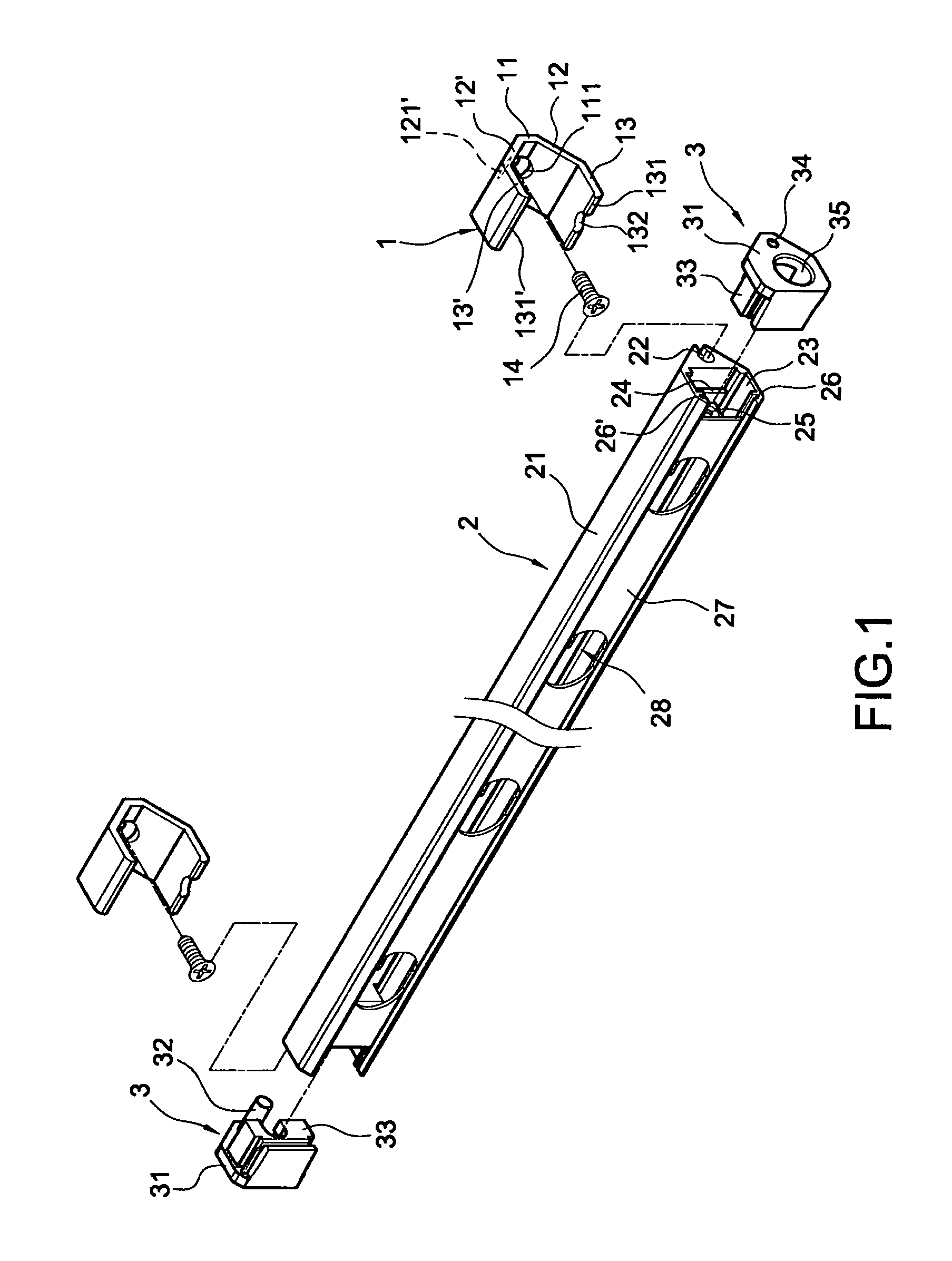
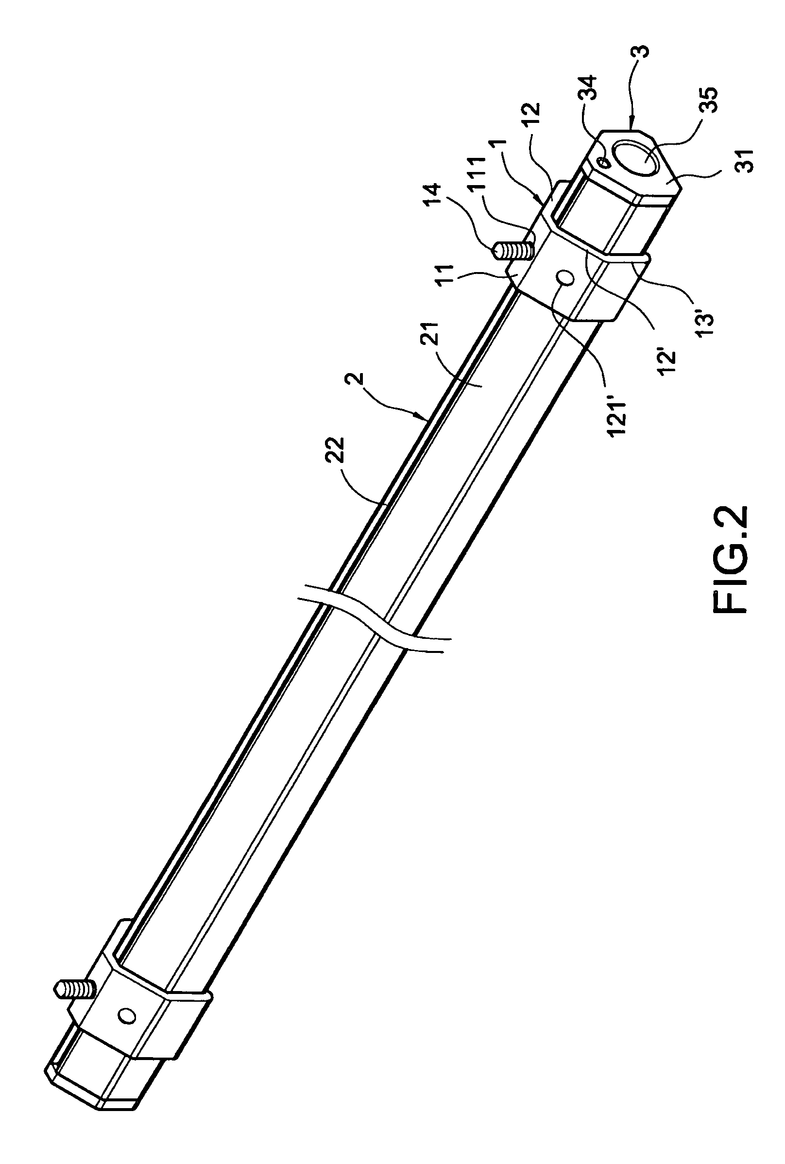
[0023]FIG. 1 is an exploded view showing the light bar lamp and the fixing assembly of the present invention, and FIG. 2 is an assembled view showing external appearance of the light bar lamp and the fixing assembly of the present invention. As shown in these figures, the assembly for fixing a light bar lamp of the present invention includes a polygonal fixing seat 1, a polygonal light bar lamp 2 and two covering plugs 3.

[0024]The polygonal fixing seat 1 is one-side-opened pentagonal or hexagonal and made of metal or plastics allowing certain variability of shape. The polygonal fixing seat 1 has a bottom 11 thereon. Both edges of the bottom 11 are bent to form two symmetrical bevels 12, 12′, respectively. The two bevels 12, 12′ are bent to form two symmetrically parallel plates 13, 13′, respectively. The bottom 11, bevels 12, 12′ and parallel p...


PUM


Abstract

An assembly for fixing and connecting a polygonal LED light bar lamp includes a fixing seat, a covering plug, and an electrical connector. The fixing seat has a bottom with both edges thereof extending to form two bevels and parallel plates. The bottom and bevels have a penetrating hole, respectively. The covering plug has a cover having an insertion hole. Two electrode pins are disposed in the interior of the insertion hole. The electrical connector has a partitioning block. Both sides of the partitioning block have a protruding pillar, respectively. The protruding pillar is provided with a hollow pillar having electrodes for contacting with electrode pins. With the fixing seat being fixed on a carrier, the light bar can be held in the fixing seat with adjustable irradiating direction. Further, two light bars can be connected in series by the electrical connector.

Description

BACKGROUND OF THE INVENTION[0001]1. Field of the Invention[0002]The present invention relates to a lamp, and in particular to a fixing and connecting structure of a light bar lamp.[0003]2. Description of Prior Art[0004]Light-emitting diodes are of small volume, long life, low electricity consumption, rapid response rate, and high resistance to vibration, and thus they are widely used in lighting or backlight sources, thereby replacing traditional bulbs, small fluorescent lamps or light-emitting elements of cold cathode lamps.[0005]When the light-emitting diodes are applied to the lighting or backlight sources, the circuit board is designed to be square or rectangular shape according to the requirements for the lighting or backlight sources. For example, the circuit board is designed to be elongated, and a plurality of light-emitting diodes is soldered on the elongated circuit board, thereby forming a light bar. When this kind of LED light bar lamps are applied to a backlight source ...

Claims


Application Information

Patent Timeline
Patent Type & Authority Patents(United States)
IPC IPC(8): F21V21/00
CPCF21S2/005F21S4/008F21S8/037F21V21/088F21V21/02F21S8/033F21S8/04H01R25/145F21W2131/301F21W2131/405F21Y2101/02F21V7/0008F21S4/28F21Y2115/10
Inventor TSAI, CHENG-YUCHEN, LI-WEICHENG, SHIOU-SHIUNGLIN, CHING-HSIEN
Owner WIESON TECH CO LTD
Learn More