
Portable fishing light

Active Publication Date: 2011-06-14
HOPKINS TIMOTHY NEVIN
View PDF12 Cites 8 Cited by
  • Summary
  • Abstract
  • Description
  • Claims
  • Application Information

AI Technical Summary

Benefits of technology

[0020]Another objective is to provide a portable fishing light wherein the light wand may be easily adjusted between a stowed position for storage, and an extended position for use.

Problems solved by technology

However, the prior art does not teach a portable fishing light that includes both a white light source and a UV light source mounted on opposing surfaces of a light wand that is mounted on a flexible control arm so that white light may be directed into a vessel for use by a fisherman, and UV light may be directed outboard for illuminating fishing lines.

Method used


Image

  • Portable fishing light
  • Portable fishing light
  • Portable fishing light

Examples


Embodiment Construction

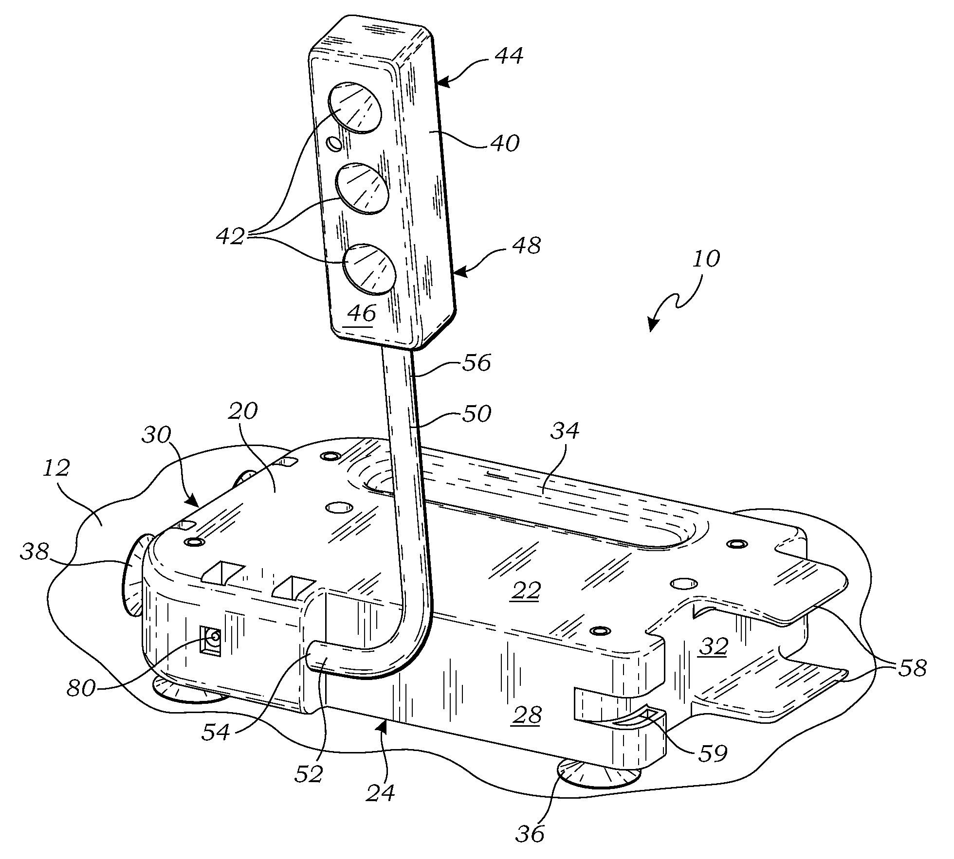
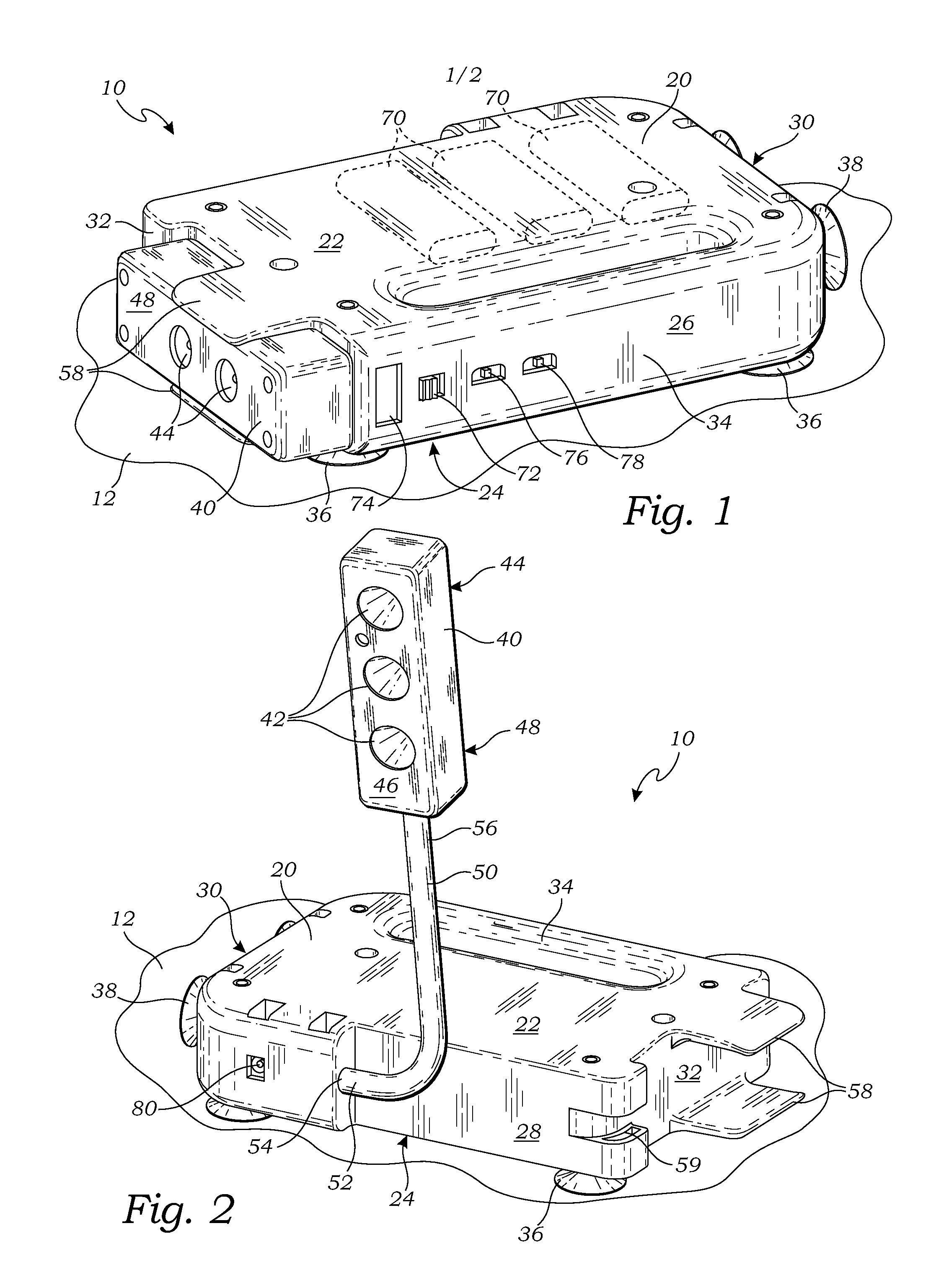
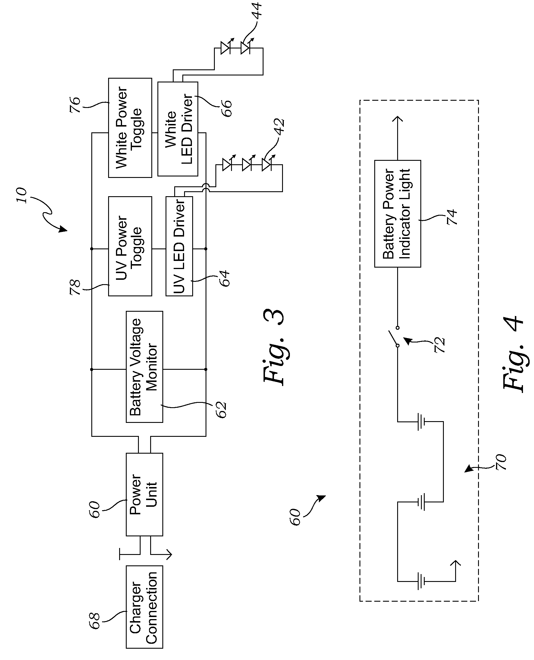
[0028]The above-described drawing figures illustrate the invention, a portable fishing light 10 for use on a boat 12 or other vehicle. The portable fishing light 10 includes both a UV light source 42 and a white light source 44. The portable fishing light 10 is particularly useful for night fishing because it directs UV light outwardly for illuminating fishing line, while directing white light inwardly for assisting the fisherman with tasks on the boat 12 (e.g., baiting a hook, removing a hook from a fish's mouth, etc.).

[0029]FIG. 1 is a front perspective view of the portable fishing light 10 illustrating a light wand 40 in a stowed position on a base housing 20. FIG. 2 is rear perspective view thereof, illustrating the light wand 40 in an extended position. As illustrated in FIGS. 1 and 2, a flexible control arm 50 of the portable fishing light 10 enables a light wand 40 to be removed from a base housing 20 of the portable fishing light 10, and positioned in almost any position so ...


PUM


Abstract

A portable fishing light has a base housing, a mounting element adapted for removably mounting the base housing on the boat, and a light wand having a white light source and a UV light source. A flexible control arm adjustably mounts the light wand to the base housing so that the light wand can be adjustably positioned relative to the base housing.

Description

CROSS-REFERENCE TO RELATED APPLICATIONS[0001]This application for a utility patent claims the benefit of U.S. Provisional Application No. 61 / 052,477, filed May 12, 2008.BACKGROUND OF THE INVENTION[0002]1. Field of the Invention[0003]This invention relates generally to portable lights, and more particularly to a portable fishing light that includes both a white light source and a UV light source mounted on opposing surfaces of an adjustable light wand.[0004]2. Description of Related Art[0005]The prior art teaches a variety of lighting system for use by fishermen during night fishing. Ohm et al., U.S. Pat. No. 6,174,078, for example, teaches a boat light system that includes a navigation light mounted on an elongate transparent housing. The housing includes, at its top, a black light, and at its bottom, a white light. The black and white lights are mounted coaxially, one above the other. The bottom of the housing includes an electrical plug for electrically connecting the system to an...

Claims


Application Information

Patent Timeline
IPC IPC(8): B63B45/06
CPCB63B45/02
Inventor HOPKINS, TIMOTHY NEVIN
Owner HOPKINS TIMOTHY NEVIN
Learn More