
Illumination system for luminaires and display devices

a technology of illumination system and display device, which is applied in the direction of planar/plate-like light guides, lighting and heating apparatus, instruments, etc., can solve the problems of poor uniformity of light emitted from the light guide plate to the image display device, uniform light emission throughout the matrix, and relatively poor uniformity. , to achieve the effect of improving uniformity

Inactive Publication Date: 2011-06-14
SIGNIFY HLDG BV
View PDF19 Cites 17 Cited by
  • Summary
  • Abstract
  • Description
  • Claims
  • Application Information

AI Technical Summary

Benefits of technology

This solution enhances light uniformity and reduces glare by mixing and distributing light uniformly across the panel, improving the color-rendering index and extending the lifespan of luminescent materials by reducing exposure to high temperatures and light flux.

Problems solved by technology

However, due to variations of emission characteristics of the LEDs in the plurality of LEDs, such as intensity and / or color variations between the emission of the LEDs, the uniformity of light emission throughout the matrix of LEDs is relatively poor, resulting in a relatively poor uniformity of the light emitted from the light guide plate to the image display device.
This relatively poor uniformity is clearly visible on the image display device.
This process, also commonly known as binning, is a relatively costly solution.
Direct glare is a visual discomfort resulting from insufficiently shielded light sources.

Method used


Image

  • Illumination system for luminaires and display devices
  • Illumination system for luminaires and display devices
  • Illumination system for luminaires and display devices

Examples


Embodiment Construction

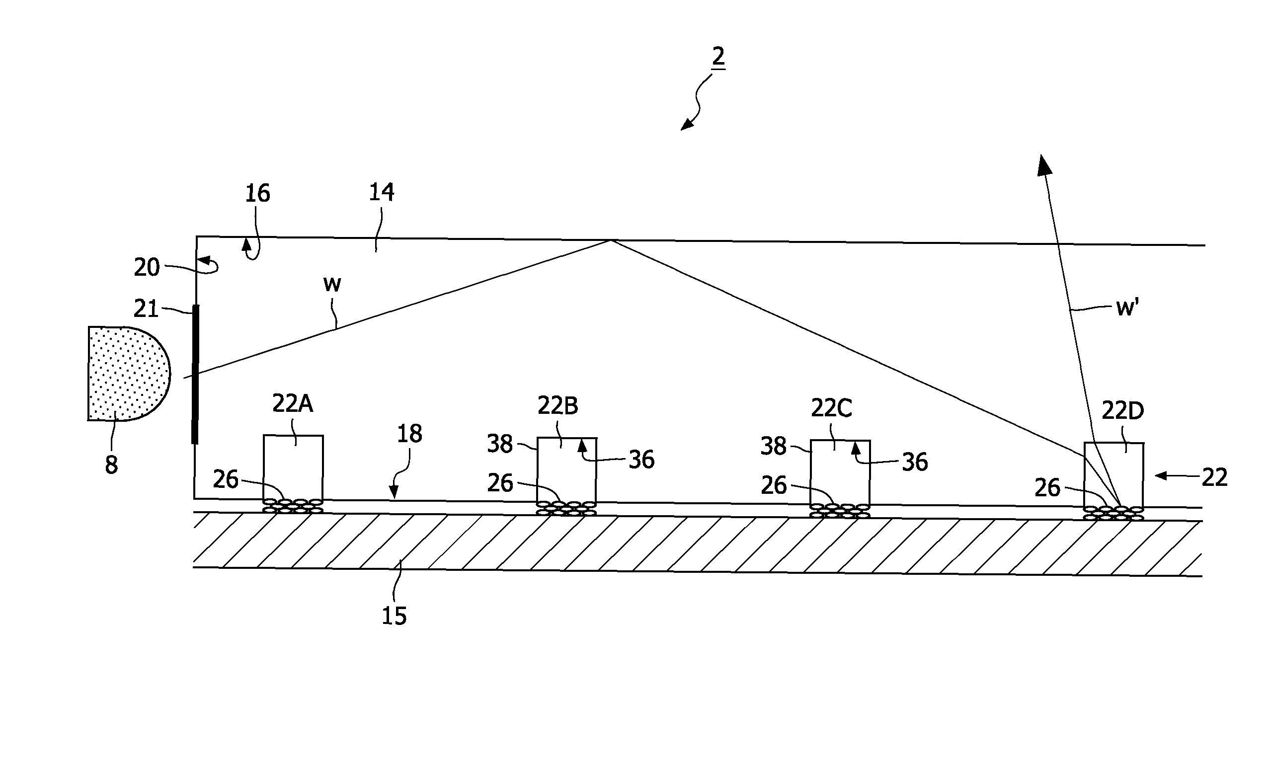
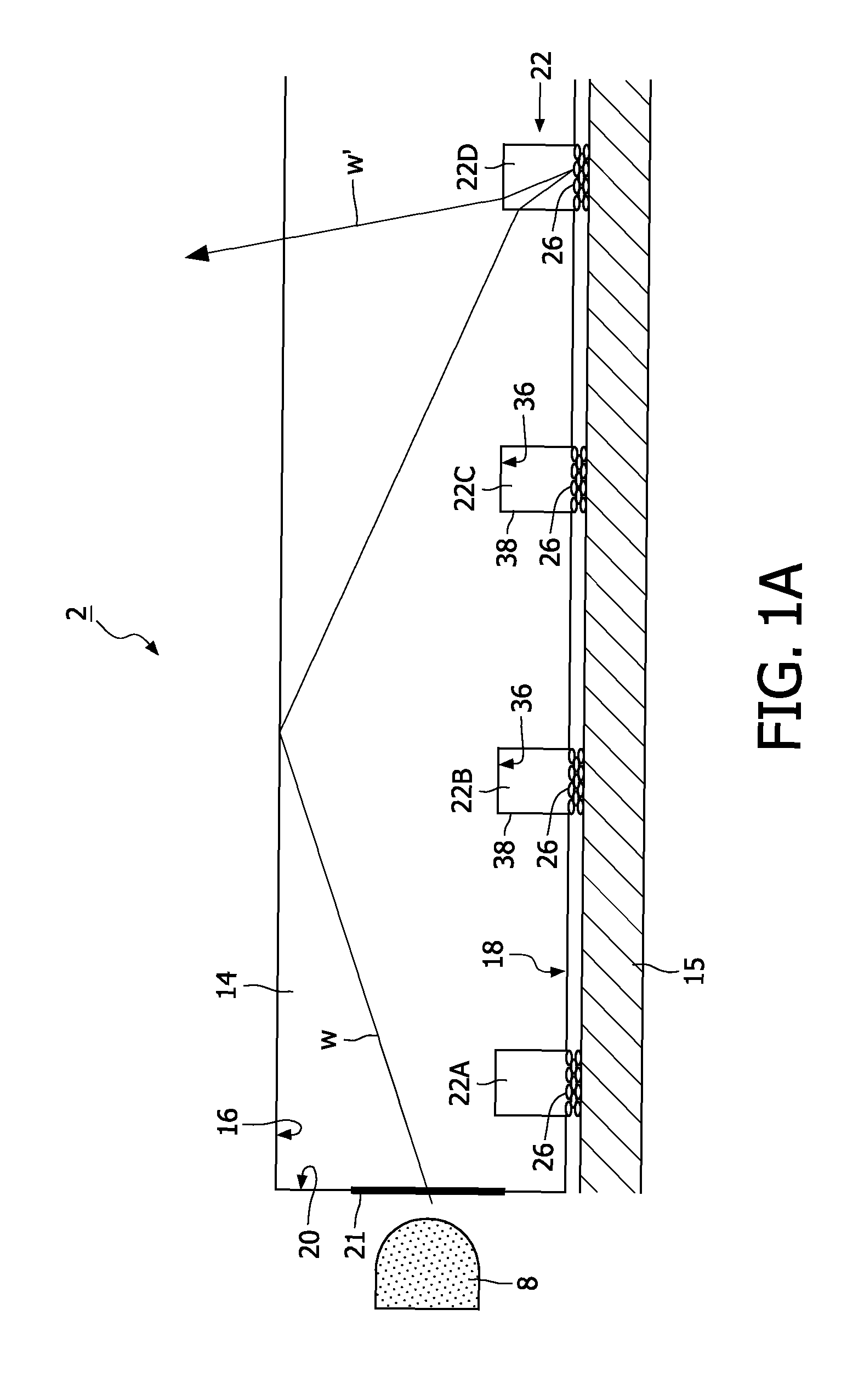
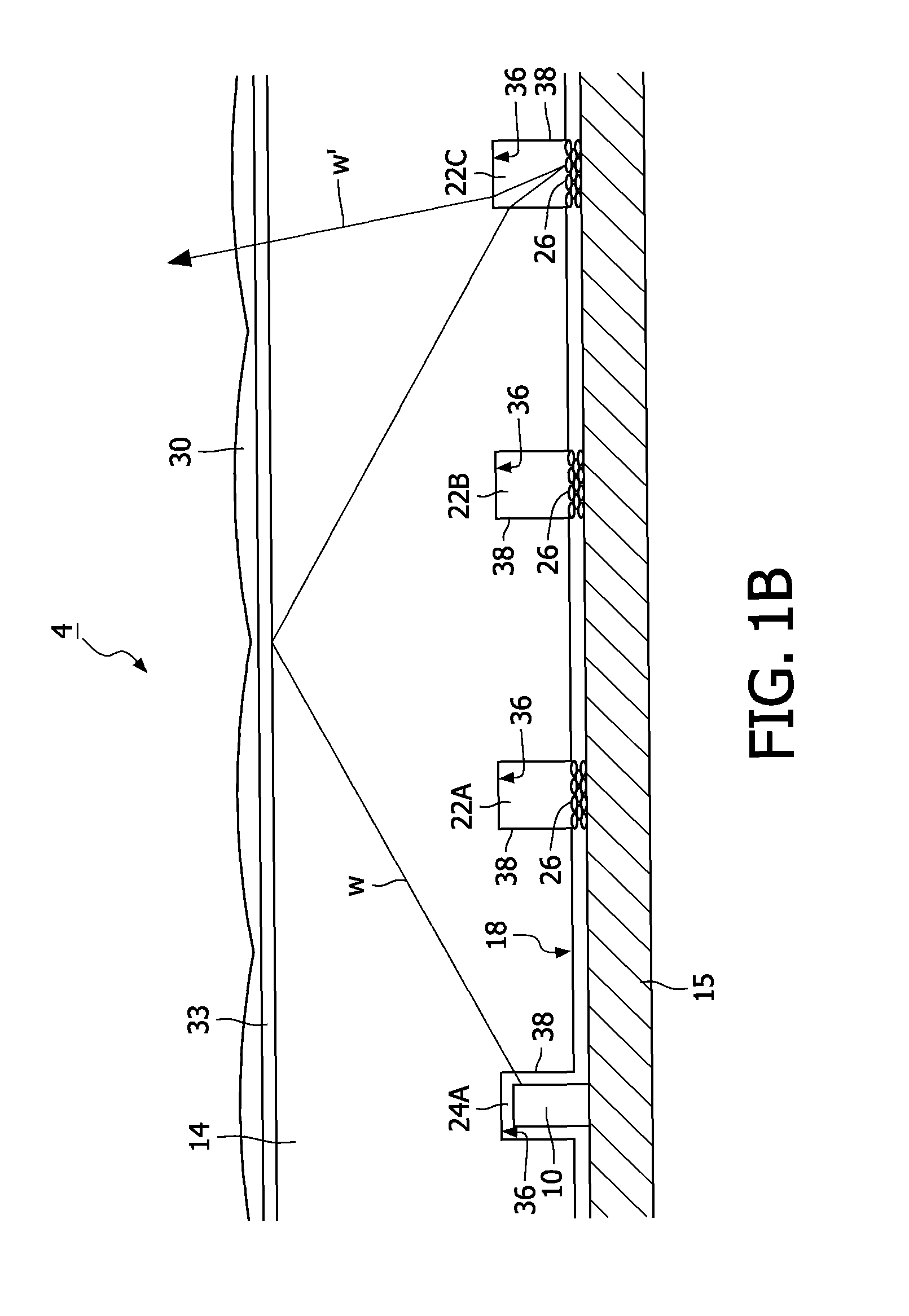
[0036]FIGS. 1A and 1B are cross-sectional views of an illumination system 2, 4 according to the invention. The illumination system 2, 4 comprises at least one light source, for example, a light-emitting diode 8, 10 (further also referred to as LED) for emitting light of a predominant wavelength R, G, B, UV, W, for example, the predominant wavelength White W (see FIG. 1A) or, for example, the predominant wavelength Ultraviolet UV (see FIG. 2). The illumination system 2, 4 further comprises a light-transmitting panel 14 which comprises a light-emitting window 16, a rear wall 18 situated opposite said light-emitting window 16, and edge walls 20 extending between the light-emitting window 16 and the rear wall 18. The light-transmitting panel 14 is arranged to couple at least part of the light W emitted by the LED 8, 10 into the light-transmitting panel 14. This can be done, for example, via the edge wall 20 comprising, for example, a light entrance window 21 (see FIG. 1A) or, for exampl...


PUM


Abstract

The invention relates to an illumination system (4) comprising at least one light source (10) for emitting light of a predominant wavelength (W), and a light-transmitting panel (14) which comprises a light-emitting window (16), a rear wall (18) situated opposite said light-emitting window, and edge walls (20) extending between the light-emitting window and the rear wall. Light from the LED is coupled into the light-transmitting panel and is transported substantially via total internal reflection. The rear wall is provided with a two-dimensional array of recesses (22, 24). A sub-set of recesses (22) is distributed substantially regularly on the rear wall. Each recess (22A, 22B, 22C) from the sub-set (22) comprises scattering material (26). When light from the light-transmitting panel reaches the scattering material of the recess, part of the light (W′) is coupled out of the light-transmitting panel via scattering. The regular distribution of the scattering material on the rear wall improves the uniformity of the light emitted via the light-emitting window. In an embodiment of the illumination system, the scattering material comprises a luminescent material (28), which absorbs light of the predominant wavelength (UV) and emits light of a further predominant wavelength (R, G, B).

Description

[0001]This application is a national stage application under 35 U.S.C. §371 of International Application No. PCT / IB2007 / 053699 filed on Sep. 13, 2007, and published in the English language on Mar. 27, 2008 as International Publication No. WO / 2008 / 035256, which claims priority to European Application No. 06120897.1 filed on Sep. 19, 2006, incorporated herein by reference.FIELD OF THE INVENTION[0002]The invention relates to an illumination system comprising a light source and a light-transmitting panel comprising a light-emitting window, a rear wall situated opposite said light-emitting window, and edge walls extending between the light-emitting window and the rear wall.[0003]The invention also relates to a luminaire and a display device.BACKGROUND OF THE INVENTION[0004]Such illumination systems are known per se. They are used, inter alia, as luminaires for general lighting purposes, for example, for office lighting or shop lighting, for example, shop-window lighting or lighting of (t...

Claims


Application Information

Patent Timeline
Patent Type & Authority Patents(United States)
IPC IPC(8): F21V7/04
CPCG02B6/004G02B6/0036
Inventor IJZERMAN, WILLEM L.CORNELISSEN, HUGO J.
Owner SIGNIFY HLDG BV
Learn More