Ink cartridge structure for pens

a technology of ink cartridges and pens, applied in the direction of ink reservoir pens, writing connectors, printing, etc., can solve the problems of ink cartridges, inability to roll smoothly, ink cartridges, and easy damage to the writing tip or ball point of the structure, and achieve the effect of smooth writing

Inactive Publication Date: 2011-06-14
SHEU RONG LIN
View PDF9 Cites 11 Cited by
  • Summary
  • Abstract
  • Description
  • Claims
  • Application Information

AI Technical Summary

Benefits of technology

[0009]The primary purpose of the present invention is to provide novel design of an ink cartridge structure and in particular to an ink cartridge structure that comprises a resilient device directly arranged at an end of the ink cartridge so that when a pen that incorporates the ink cartridge accidentally falls onto the ground, the resilient device effectively absorbs most of the impact energy so as to protect the ink cartridge from being damaged or incurring ink discontinuity. In accordance with the present invention, a connection bar is fit to an upper end of the ink cartridge with a resilient element provided thereon and a retention bar is fit to the resilient element so that the resilient element is directly coupled to the end of the ink cartridge. Thus, the ink cartridge structure can be simply deposited into a pen barrel and can be arbitrarily replaced by a new one. Compression of the resilient element allows for control of the up and down movement of the ink cartridge. The connection bar of the ink cartridge is provided with a threaded section to engage an internal thread formed in the upper end of the ink cartridge with adjustability of the penetration depth of the connection bar screwed into the ink cartridge to control the biasing force induced on the ink cartridge. A vent hole is formed in a fitting portion of the connection bar so that when the retention bar is depressed, an amount of air is pumped into the ink cartridge to drive the ink contained in the ink cartridge toward the writing tip of the ink cartridge thereby ensuring smooth writing without incurring ink discontinuity and allowing adjustment of line width scratched with the ink cartridge.

Problems solved by technology

Such a structure suffers easy damage to the writing tip or ball point of the ink cartridge due to the fact that no cushioning is provided to absorb impact energy that is applied to the writing tip or ball point when the writing tip is hit by for example an external force or falling onto the ground.
When the ball point is damaged, the ball cannot roll smoothly and discharge of ink through the ball is interrupted.
The worst case is that the pen is totally broken and cannot be used for writing.
This is certainly very troublesome.
This makes the pen an uneconomic device.
(3) The lines drawn with the conventional ink cartridge is of a fixed width and the line may get easily broken when the force applied to the pen in the writing process is too light.
Other disadvantage is also known for discontinuous line that a pen that has been stowed in an up-side-down manner for a substantial period of time may draw.

Method used


Image

  • Ink cartridge structure for pens
  • Ink cartridge structure for pens
  • Ink cartridge structure for pens

Examples


Embodiment Construction

[0021]The following descriptions are of exemplary embodiments only, and are not intended to limit the scope, applicability or configuration of the invention in any way. Rather, the following description provides a convenient illustration for implementing exemplary embodiments of the invention. Various changes to the described embodiments may be made in the function and arrangement of the elements described without departing from the scope of the invention as set forth in the appended claims.

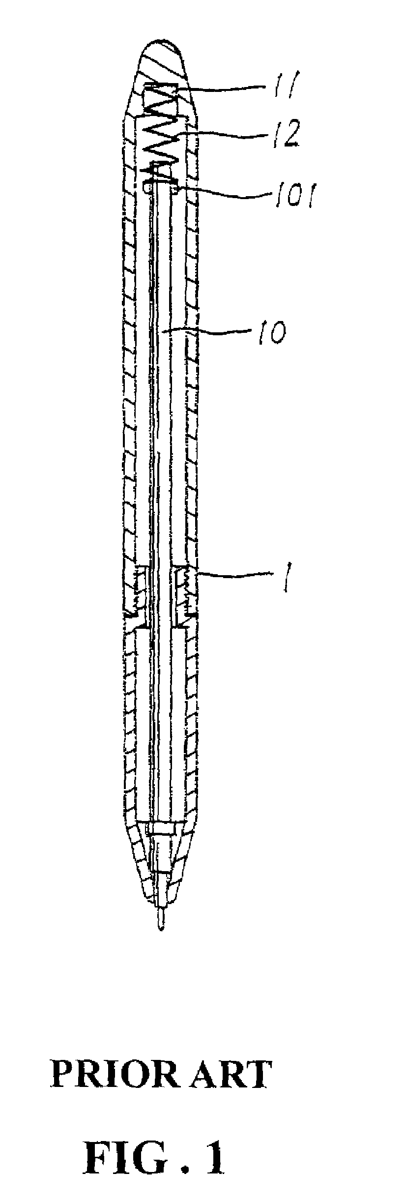
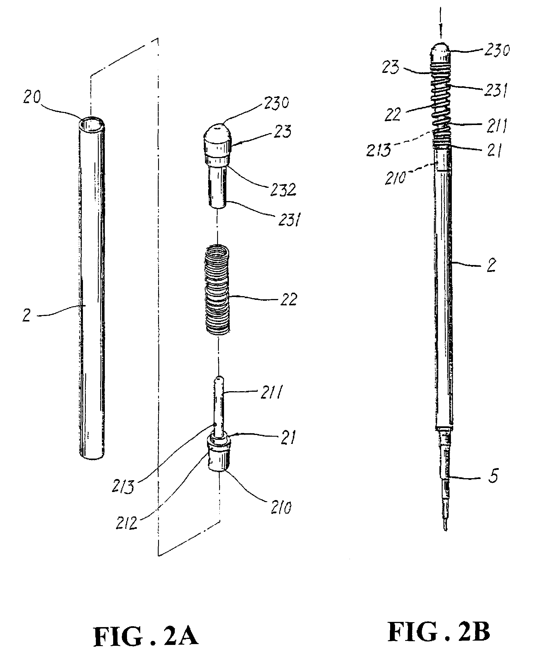
[0022]The present invention provides a design of an ink cartridge incorporating a resilient device, which ink cartridge, as particularly shown in FIGS. 2A and 2B that illustrate the ink cartridge device in accordance with the present invention, comprises an outer casing 4, an ink cartridge bar 2, a connection bar 21, a resilient element 22, and a retention bar 23. The ink cartridge bar 2 is a hollow member forming in an upper end thereof a fitting hole 20 and is fit to an ink cartridge 5 or is in...


PUM


Abstract

An ink cartridge structure includes a resilient device coupled to an ink cartridge for absorbing impact energy acting on the ink cartridge for protection of the ink cartridge. The resilient device includes a connection bar mounted to the ink cartridge and is coupled to a retention bar that is accessible by a user with a resilient element therebetween so that the resilient element provides cushioning to the ink cartridge. The connection bar is partially fit into a hollow portion of the retention bar and forms a vent hole that is in communication with the ink cartridge so that when the retention bar, under the resilient support by the resilient element, is manually moved reciprocally with respect to the connection bar, air is pumped, through the vent hole, into the ink cartridge to force the ink contained in the ink cartridge to ward a writing tip.

Description

BACKGROUND OF THE INVENTION[0001](a) Technical Field of the Invention[0002]The present invention relates to a novel design of an ink cartridge structure, and in particular to an ink cartridge structure that comprises a resilient device for cushioning impact and thus protecting the ink cartridge from being damaged or incurring ink discontinuity, wherein the resilient device in arranged at an end of the ink cartridge and an upper end of the ink cartridge forms an internal thread to engage a threaded section formed on a connection bar for adjustability of the biasing force induced by the resilient device and thereby adjusting the force that the resilient device applies to the ink cartridge and wherein a vent hole is provided in the coupling between the resilient device and the ink cartridge so that when the resilient device is compressed, air is pumped into the ink cartridge through the vent hole to keep the ink contained in ink cartridge being driven toward a writing tip of the ink ca...

Claims


Application Information

Patent Timeline
Patent Type & Authority Patents(United States)
IPC IPC(8): B43K24/02
CPCB43K7/02B43K23/128B43K17/00B43K7/03
Inventor SHEU, RONG-LIN
Owner SHEU RONG LIN
Why Eureka
Try Eureka