Unit cuvette for analyzing a biological fluid, automatic device for in vitro analysis

a technology of biological fluid and cuvette, which is applied in the field of unit cuvette for analyzing biological fluid, and automatic device for in vitro analysis, can solve the problems of difficulty if not impossible to carry out different tests on the cuvettes of a given block, increase the cost of a cuvette, and difficulty in removing such a block, etc., and achieves the effect of convenient detachment, simple and inexpensive manufacturing and maintenance, and substantially reduced operating cos

Active Publication Date: 2011-06-14
ALAIN ROUSSEAU +1
View PDF21 Cites 19 Cited by
  • Summary
  • Abstract
  • Description
  • Claims
  • Application Information

AI Technical Summary

Benefits of technology

[0011]Several cuvettes according to the invention can therefore be assembled together so as to form trays that are very easy to store, in a confined space. In addition, it is very easy to detach a unit cuvette from such a tray, even automatedly, thereby making this type of cuvette particularly easy to use in an automatic analyzer for in vitro analysis.
[0012]Moreover, these cuvettes are multipurpose cuvettes. This is because they include a raceway for measuring the clotting time of blood by detecting the movements of a ball. However, the presence of a ball is optional, and the cuvette can be used for any type of test, without the impediment due to the ball or to the particular shape of the bottom of the cuvette. The presence of a lowermost point in the bottom of the cuvette, formed by the raceway, has in addition the advantage of allowing liquids to be drawn in with a very small dead volume and of making it easier to wash the magnetic particles.
[0022]Thanks to this automatic analyzer and the cuvettes used, which can serve for various types of test using different measurement technologies, it is possible to carry out these various tests and to control them in an improved manner compared with the prior art. This is because processes involving lengthy (immunology) measurements or those requiring the continuous observation of the phenomenon (clotting) to be measured may be carried out away from the ring, on the corresponding stations, and therefore do not constitute bottlenecks in the case of rapid-process (biochemistry) tests. The cuvettes may be stored in tray form in the feed magazine, while still being easily detachable from one another, on demand.
[0023]The automatic analyzer according to the invention is multipurpose, but simple and inexpensive to manufacture and to maintain. Furthermore, its operating cost is substantially lower than that of the controllers of the prior art. This means that the number of machines per laboratory can be reduced, thus helping to reduce the public health expenditure.

Problems solved by technology

Firstly, when the cuvettes disclosed in document EP 0 325 874 are used individually, it is difficult or time-consuming to store them in an ordered manner, which saves space, without it being tricky to separate the cuvettes from one another by means of a controller. Conversely, when several cuvettes are formed as a single block, storage is easier, even if a greater volume may be required. However, handling such a block may prove awkward in certain applications and, in any case, it is difficult if not impossible to carry out different tests on the cuvettes of a given block, unless a very specific analyzer is provided.
Of course, it is possible to use these cuvettes for performing other analyses or measurements on the biological fluid that they contain, but this involves the following drawbacks:the cost of a cuvette is needlessly increased because of the unnecessary presence of a ball on the one hand, and means provided on the cuvette for preventing the ball from escaping on the other;the presence of a ball may prove problematic in the case of certain tests (especially immunology tests using magnetic particles); andin the case of photometric measurements, it is necessary to increase the reaction volume so as to cover the ball with a sufficient height so as to carry out the optical measurement escaping the ball.
The cost of the test is therefore increased owing to unnecessary amounts of reactants.

Method used


Image

  • Unit cuvette for analyzing a biological fluid, automatic device for in vitro analysis
  • Unit cuvette for analyzing a biological fluid, automatic device for in vitro analysis
  • Unit cuvette for analyzing a biological fluid, automatic device for in vitro analysis

Examples


Embodiment Construction

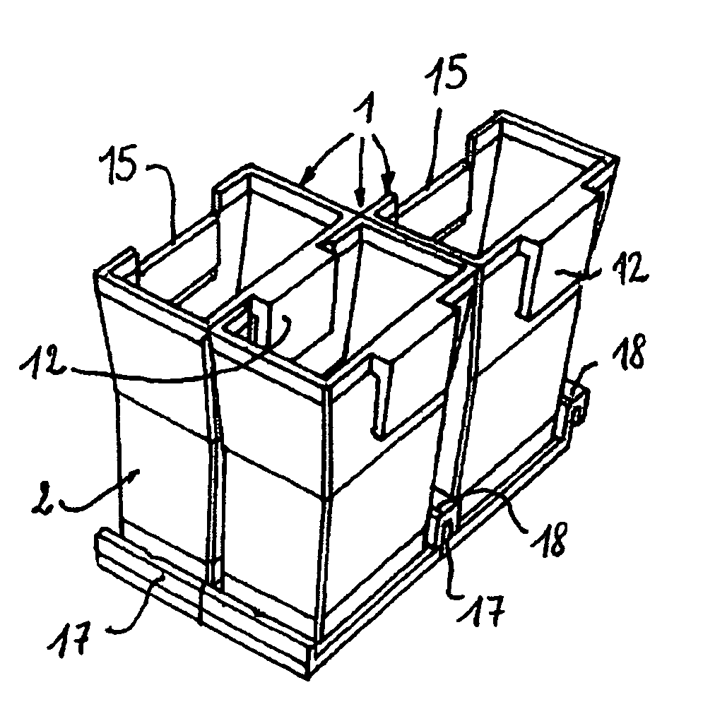
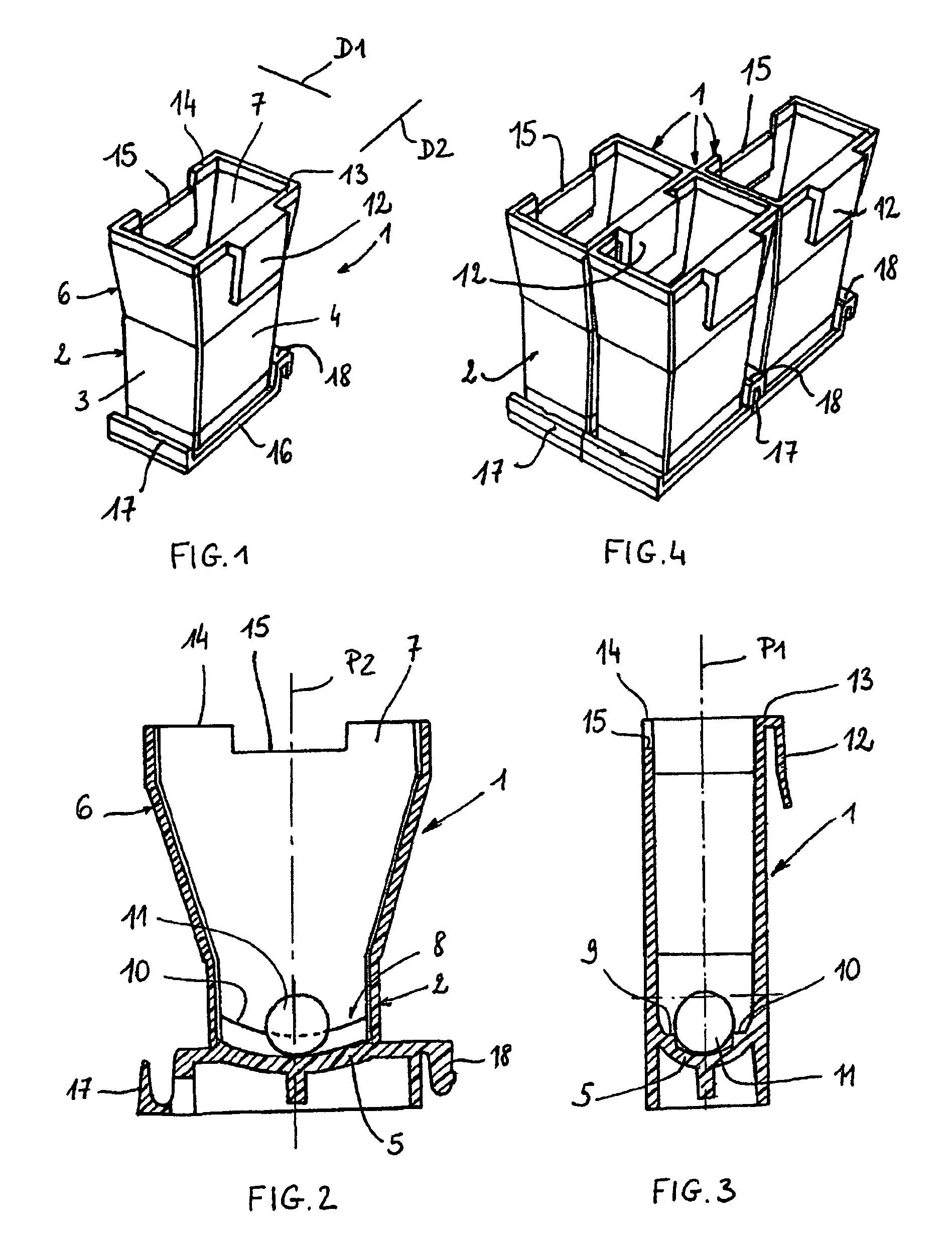
[0035]As illustrated in FIG. 1, a cuvette 1 has a lower part 2 of approximately parallelepipedal shape, having large faces 3, small faces 4 and a bottom 5. The lower part 2 has a length of around 8 mm and a width of around 4 mm. This makes it possible to obtain a reaction mixture with a minimum volume of 200 μl, thereby limiting the consumption of reactants, while still maintaining optical paths sufficient for the spectrophotometric and turbidimetric (clotting) measurements.

[0036]The lower part 2 of the cuvette 1 is extended by a funnel-shaped upper part 6 flaring out on the opposite side from the bottom 5, in the form of a truncated cone or truncated pyramid, and forming an upper opening 7. This makes it possible to increase the rinsing volume or the reaction volume, to create a wide opening and to make it easier to rinse the nanoparticles for immunology tests. A cuvette 1 having a height of around 22 mm may contain up to 650 μl.

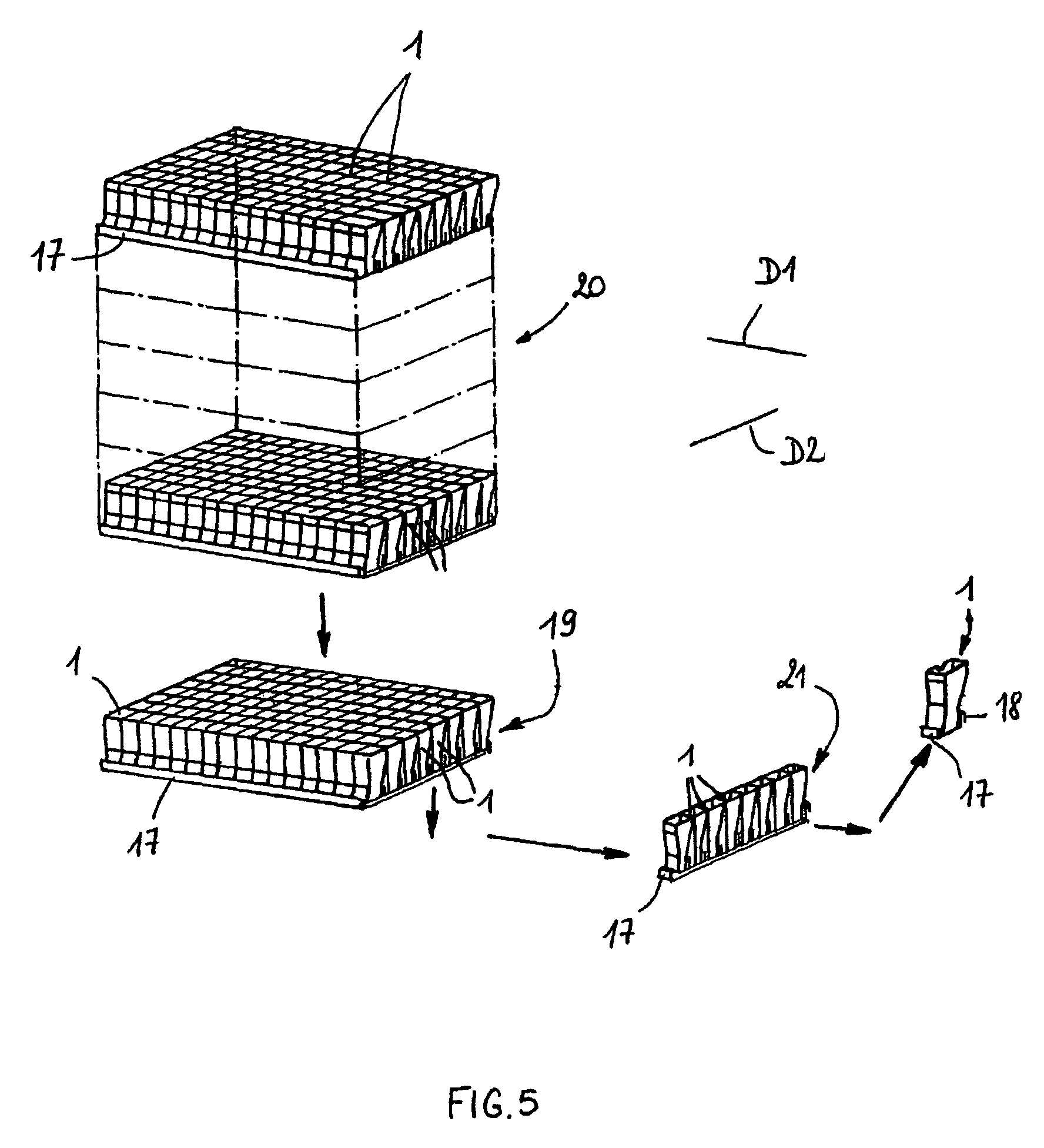
[0037]The transverse direction D1 is defined as the d...


PUM


Abstract

The bottom of the cuvette comprises a curved raceway placed so as to guide the oscillating movement of a ball inserted into the cuvette. In addition, the cuvette comprises means of attachment, in two perpendicular directions, to adjacent unit cuvettes. The cuvettes can thus be stored as plates in a feed magazine of an analytical device. The analytical device comprises several stations placed around a rotary ring. Only where it is desired to determine the clotting time of the blood contained in the cuvette a ball is introduced into the latter, at a ball distribution post. The cuvette equipped in this way is then brought to a station where the test is carried out. The major advantage of the invention is the polyvalence of the cuvette and of the analytical device.

Description

BACKGROUND OF THE INVENTION AND DESCRIPTION OF THE PRIOR ART[0001]The present invention relates to a unit cuvette capable of containing a biological fluid, in order to analyze said fluid, and to an automatic analyzer comprising such cuvettes for in vitro analysis.[0002]Document EP 0 325 874 teaches a cuvette for determining the clotting time of blood. For this purpose, the bottom of the cuvette comprises a curved raceway with an upwardly directed concavity, on which a ferromagnetic ball is placed and driven in a periodic movement under the effect of an external magnetic field. By detecting the variations in amplitude and / or frequency of the movement of the ball it is possible to measure the clotting time. This measurement is carried out by means of a densitometer placed in such a way that the light beam that it produces is approximately tangential to the ball when it is at the lowermost point of the raceway. The cuvettes may be used either individually or in blocks of several cuvett...

Claims


Application Information

Patent Timeline
Patent Type & Authority Patents(United States)
IPC IPC(8): B01L3/00
CPCB01L3/50855G01N35/025B01L2200/025G01N2035/0465G01N2035/041G01N21/03G01N35/00B01L3/00
Inventor ROUSSEAU
Owner ALAIN ROUSSEAU
Why Eureka
Try Eureka