Movable contact element and switch using the same

a technology of movable contact and switch, which is applied in the direction of contact, emergency protective device, emergency actuator, etc., can solve the problems of complicated construction of switch b>150/b>, complicated operation body, and high cost of movable contact b>102/b> and switch b>150/b>, and achieves simple construction, simple construction, and simple

Inactive Publication Date: 2011-06-14
PANASONIC CORP
View PDF17 Cites 5 Cited by
  • Summary
  • Abstract
  • Description
  • Claims
  • Application Information

AI Technical Summary

Benefits of technology

[0017]The present invention provides a movable contact element, which has a simple construction and can perform various operations, and a switch using the same.
[0018]The movable contact element according to the present invention includes a movable contact having a dome shape, a cover sheet, and a pressure sensitive conductive sheet. On a lower surface of the cover sheet, the movable contact is bonded. On a top surface of the pressure sensitive conductive sheet, the cover sheet is stacked. Through such a construction, it is possible to obtain a movable contact element which has a simple construction and can perform various operations.
[0019]Further, the switch according to the present invention includes a substrate, a movable contact element, and a fixed contact. The movable contact element has a movable contact having a dome shape, a cover sheet having the movable contact bonded to its lower surface, and a pressure conductive sheet having the cover sheet stacked on its top surface. The fixed contact is formed on a top surface of the substrate so as to face a lower surface of the pressure sensitive conductive sheet. Through such a construction, it is possible to obtain a switch which has a simple construction and can perform various operations.

Problems solved by technology

Further, an operation body having a complicated shape is also required.
Therefore, the number of parts composing switch 150 increases, and the construction of switch 150 becomes complicated.
As a result, movable contact 102 and switch 150 become expensive.

Method used


Image

  • Movable contact element and switch using the same
  • Movable contact element and switch using the same
  • Movable contact element and switch using the same

Examples


first embodiment

[0040]A first embodiment of the present invention will be described with reference to FIGS. 1 to 8.

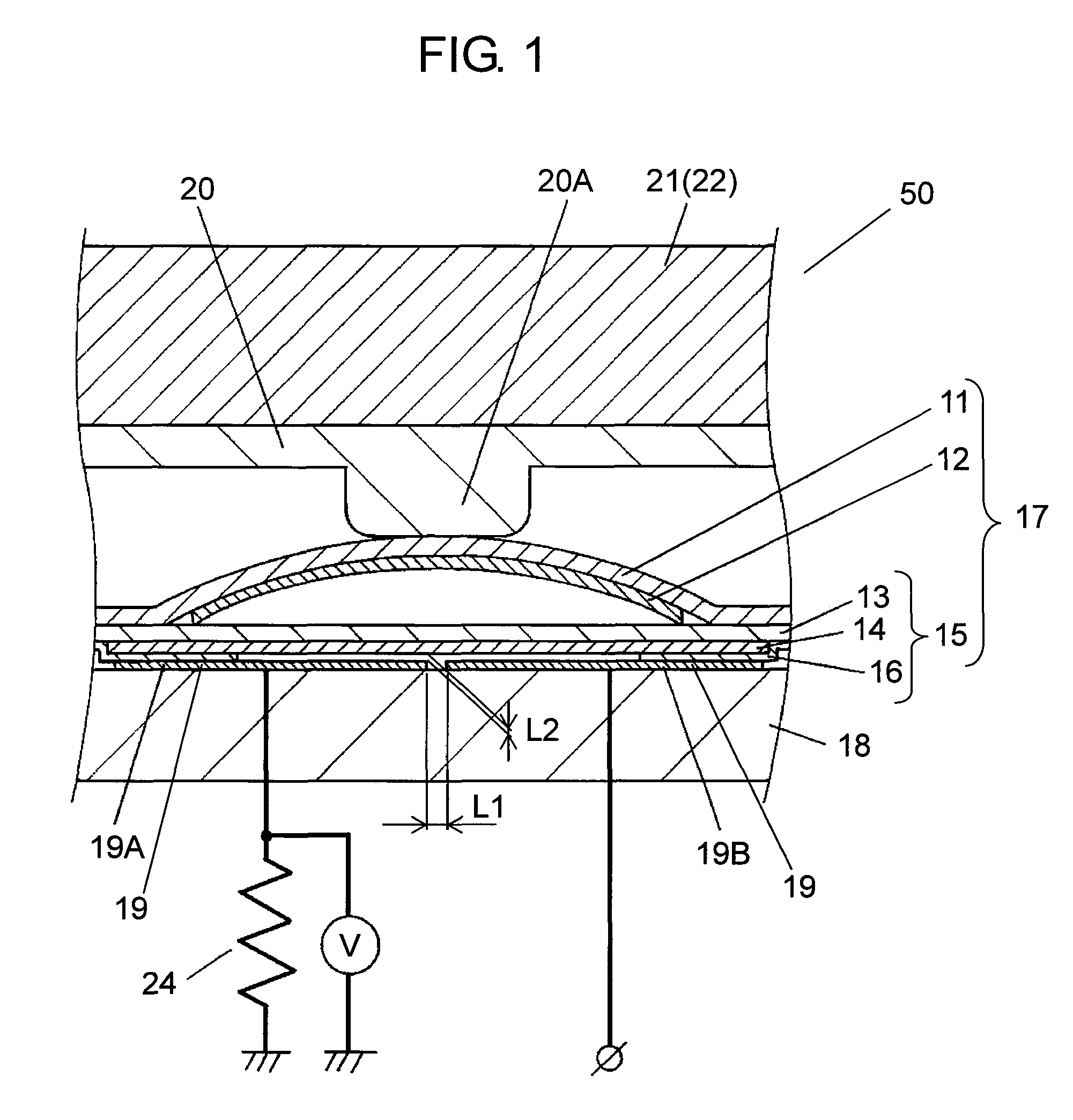
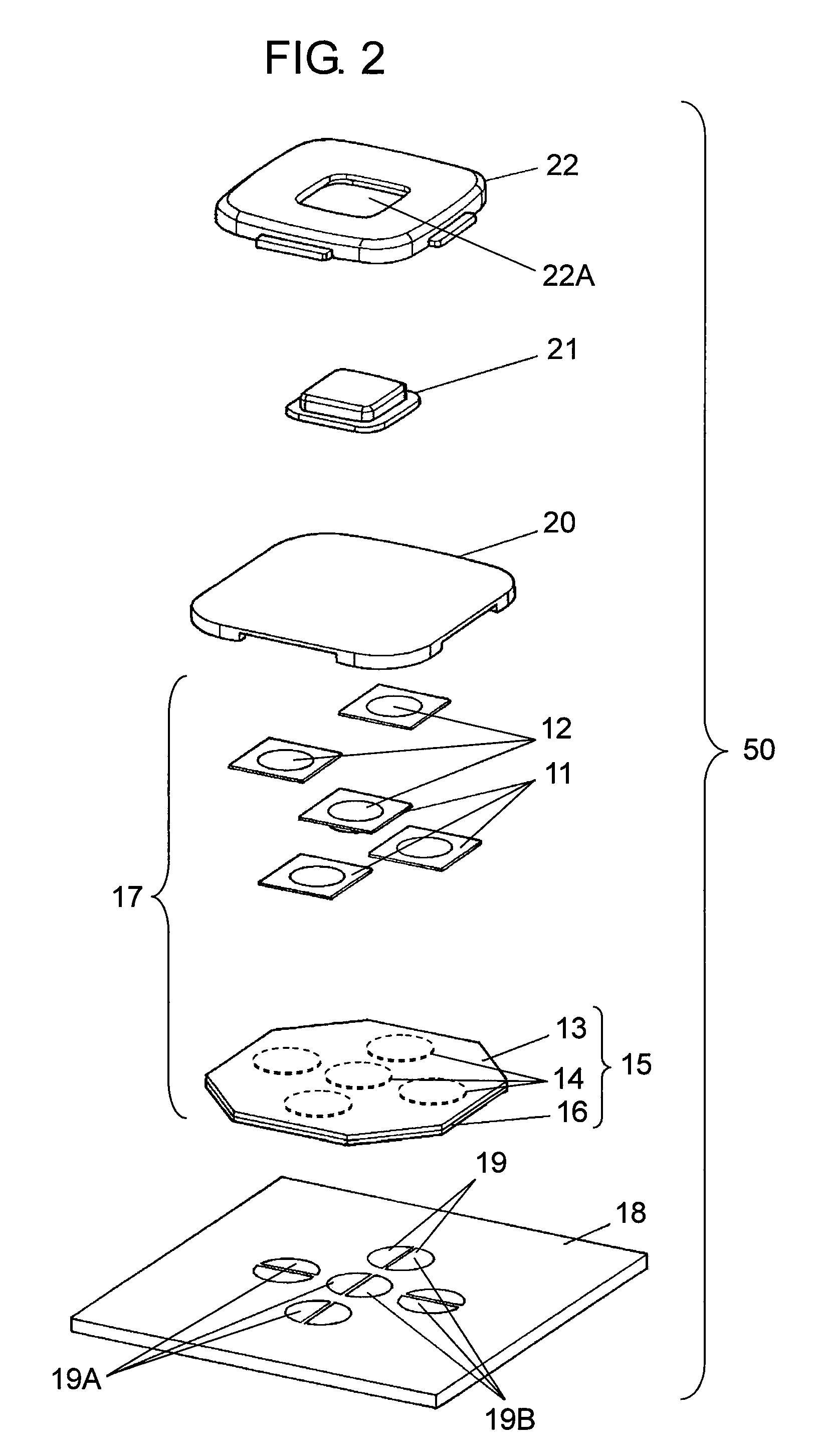
[0041]FIG. 1 is a cross-sectional view of switch 50 according to the first embodiment of the present invention. FIG. 2 is an exploded perspective view of switch 50. FIGS. 3A and 3B are perspective views of switch 50. FIG. 4 is a cross-sectional view of pressure sensitive conductive sheet 15 (hereinafter, referred to as sheet 15) used in switch 50. FIG. 5 is a cross-sectional view of switch 50 when a pressing operation is performed. FIG. 6 is a graph showing characteristics of switch 50. FIG. 7A is a plan view of display screen 30 of an electronic apparatus (not shown) on which switch 50 is mounted. FIG. 7B is a plan view of another type of display screen 30 of the electronic apparatus on which switch 50 is mounted. FIG. 8A is a plan view of fixed contact 19 used in switch 50. FIG. 8B is a plan view of another type of fixed contact 19 used in switch 50.

[0042]As shown in FIGS. 1 and 2, s...

second embodiment

[0070]Hereinafter, a second embodiment of the present invention will be described with reference to FIGS. 9 to 11. In this embodiment, like reference numerals will be attached to the same components as those of the first embodiment, and the detailed descriptions thereof will be omitted.

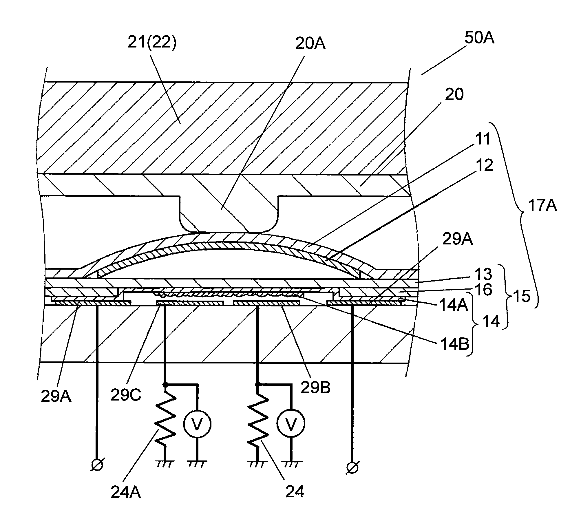
[0071]FIG. 9 is a cross-sectional view of switch 50A according to a second embodiment of the present invention. FIG. 10 is a plan view of fixed contact 29 used in switch 50A. FIG. 11 is a graph showing characteristics of switch 50A.

[0072]As shown in FIGS. 9 and 10, switch 50A has movable contacts 12 bonded to the lower surface of cover sheet 11. Further, in the switch 50A, cover sheets 11 are bonded to the top surface of pressure sensitive conductive sheet 15. Such a construction is the same as that of the first embodiment. In movable contact element 17A and switch 50A according to the second embodiment, the outer periphery of pressure sensitive conductive layer 14 is formed on a lower surface of insu...


PUM

PropertyMeasurementUnit
threshold voltage V1aaaaaaaaaa
currentaaaaaaaaaa

Abstract

A movable contact element includes a cover sheet to which a movable contact having a dome shape is bonded and which is stacked on a top surface of a pressure sensitive conductive sheet. The movable contact element is bonded to a top surface of a substrate having a fixed contact formed thereon, thereby forming a switch. Through the construction, it is possible to obtain the movable contact element, which has a simple construction and can perform various operations, and the switch using the same.

Description

BACKGROUND OF THE INVENTION[0001]1. Technical Field[0002]The present invention relates to a movable contact element used for operating various electronic apparatuses and a switch using the same.[0003]2. Background Art[0004]Recently, a variety of high-performance electronic apparatuses such as mobile phones or car navigation systems are being developed. With the development of electronic apparatuses, there is demand for a device which can perform various operations on a movable contact element used for operating the electronic apparatuses or a switch.[0005]Such a conventional movable contact element and a switch using the same will be described with reference to FIG. 15.[0006]FIG. 15 is a cross-sectional view of conventional switch 150. In FIG. 15, switch 150 has movable contact element 104, substrate 105, and fixed contacts 106. Movable contact element 104 has cover sheet 101 and movable contacts 102. Cover sheet 101 with flexibility is formed in a film shape. Each of movable contac...

Claims


Application Information

Patent Timeline
Patent Type & Authority Patents(United States)
IPC IPC(8): H01H1/10
CPCH01H13/785H01H1/029H01H13/48H01H25/041H01H2025/048H01H2239/012H01H2203/012H01H2203/02H01H2215/006H01H2215/036H01H2221/05H01H2201/036
Inventor YOSHIHARA, SATOSHIYAMAMOTO, TAMOTSUSAWADA, MASAKI
Owner PANASONIC CORP
Why Eureka
Try Eureka