Wheel suspension mechanism

a technology of suspension mechanism and wheel, which is applied in the direction of wing accessories, physical therapy, transportation and packaging, etc., can solve the problems of easy breakage of wheel sets, uneven horizontal movement, and inability to properly and adjustably mesh with the rails,

Inactive Publication Date: 2011-06-21
SIN LIN TECH
View PDF8 Cites 7 Cited by
  • Summary
  • Abstract
  • Description
  • Claims
  • Application Information

AI Technical Summary

Benefits of technology

[0008]To achieve the objective, the wheel suspension mechanism in accordance with the present invention comprises an absorber including an outer sleeve. A support spindle is rotatably received in the outer sleeve and the support spindle is rotated and reciprocally moved relative to the outer sleeve. The support spindle has an annular flange radially extending from a middle section thereof to divide the support spindle into a first section and a second section. A flexible member is compressively sleeved on the first section of the support spindle for providing a cushion effect. A wheel assembly is connected to a distal end of the second section of the support spindle of the absorber and the wheel assembly is rotatably slanted relative to the absorber for adapting to mesh with an uneven rail.
[0009]The absorber of the wheel suspension mechanism of the present invention effectively absorbs and reduces perpendicular waves form a horizontal vibration mechanism. Furthermore, the wheel assembly of the present invention is freely adjusted for meshing with the uneven rail such that a lateral movement of the wheel suspension mechanism is smooth.

Problems solved by technology

However, the rack and the base are usually formed with welding such that the rails are uneven to cause an error and the wheel sets of the conventional horizontal vibration mechanism are fixed on an underside of the rack.
Therefore, the wheel sets couldn't properly and adjustably mesh with the rails such that the mattress is reciprocally moved with irregular shaking and the conventional horizontal vibration mechanism couldn't provide a smooth horizontal movement and makes a loud noise.
Furthermore, the wheel sets of the conventional horizontal vibration mechanism provides no cushion function such that the wheel sets may be easily broken due to the horizontal vibration after being used for a period of time.

Method used


Image

  • Wheel suspension mechanism
  • Wheel suspension mechanism
  • Wheel suspension mechanism

Examples


Embodiment Construction

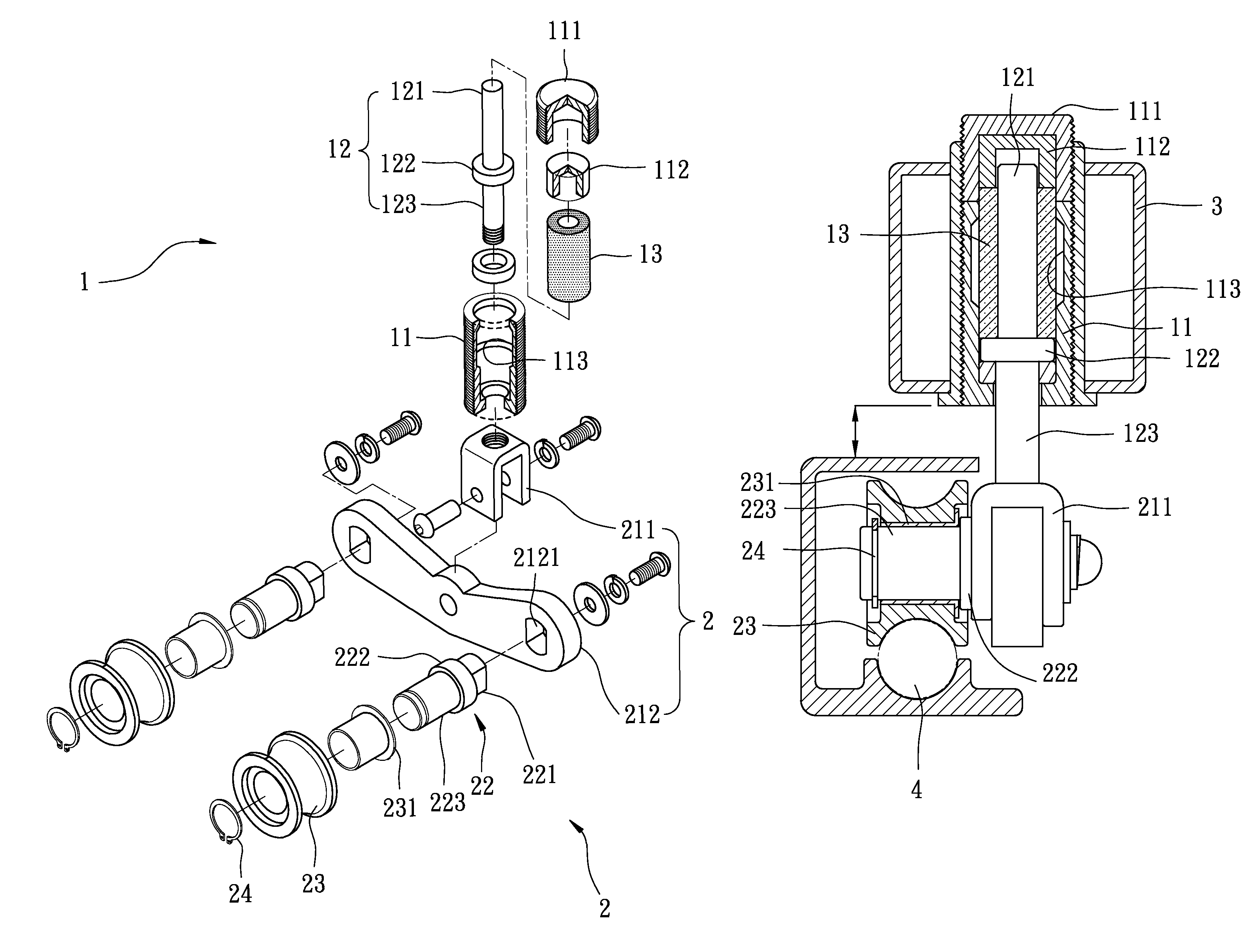
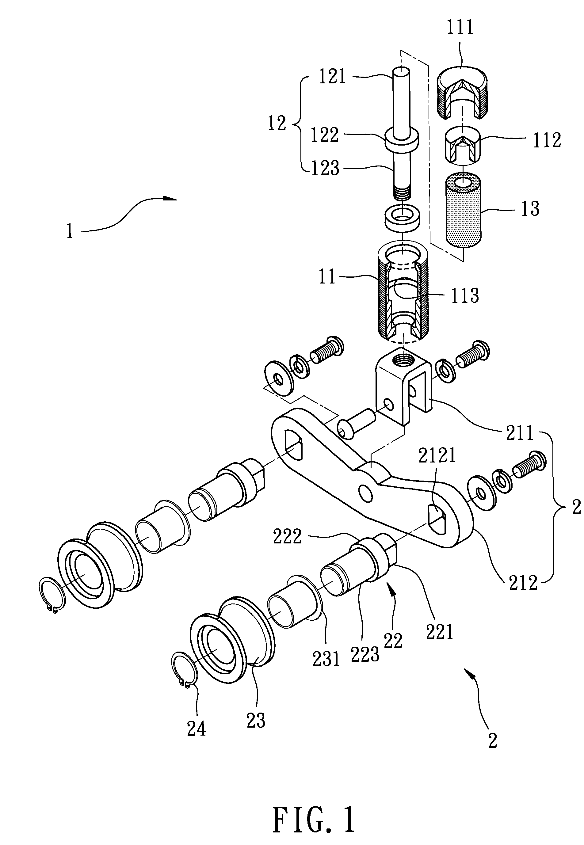
[0020]Referring to the drawings in FIGS. 1 and 5, a wheel suspension mechanism in accordance with the present invention comprises an absorber 1 and a wheel assembly 2 that is connected to the absorber 1.

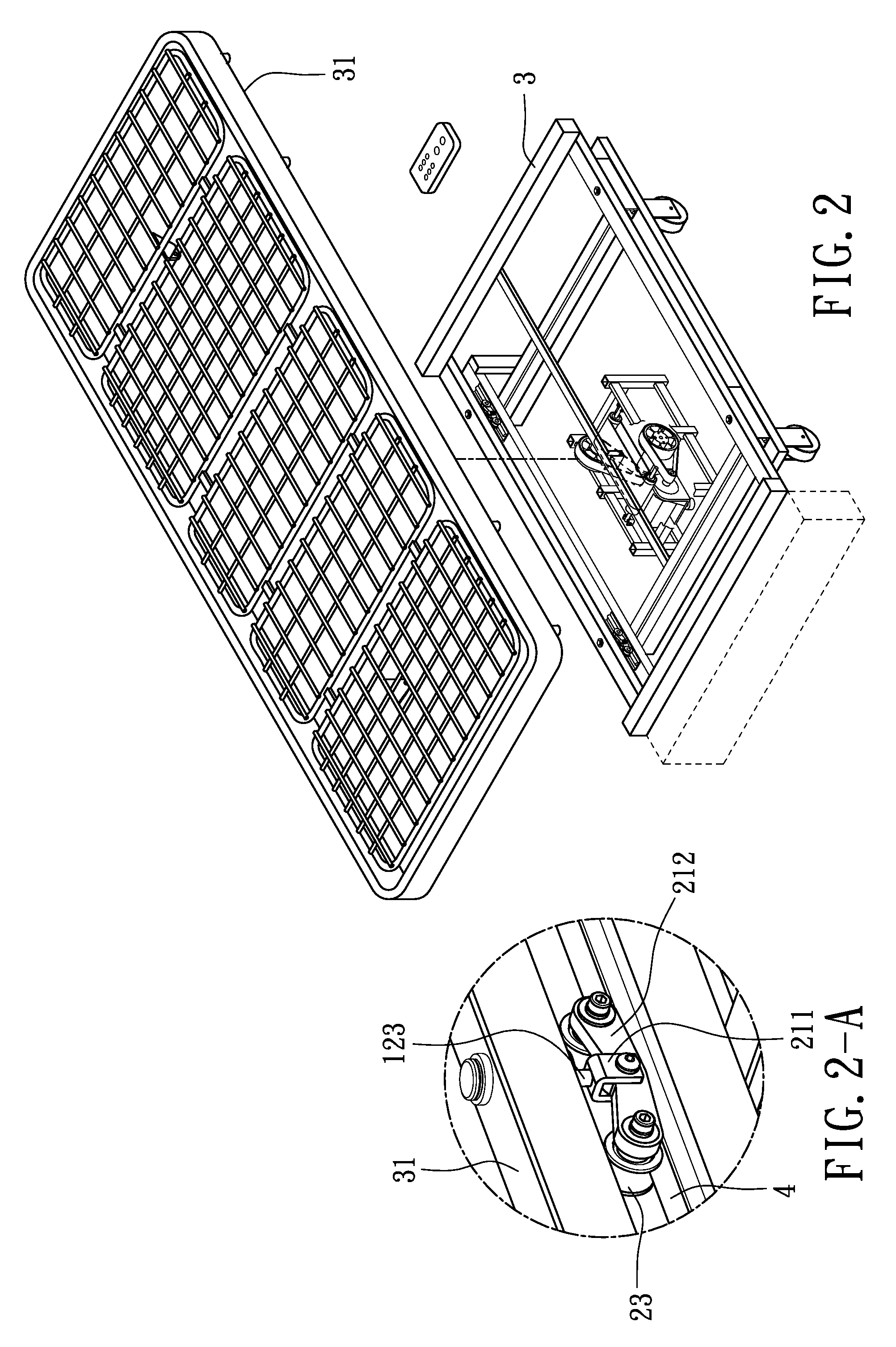
[0021]The absorber 1 includes an outer sleeve 11, a washer (not numbered) received in a bottom of the outer sleeve 11, a support spindle 12 rotatably and reciprocally received in the outer sleeve 11 and extending through the washer, a hollow flexible member 13 sleeved on the support spindle 12, a pusher 112 mounted to the flexible member 13, and an cap 111 mounted on the pusher 112. The outer sleeve 11 has a threaded outer periphery for adapting to be mounted in a horizontal vibration mechanism 3 (shown in FIG. 2). The outer sleeve 11 has an annular recess 113 laterally defined in an inner periphery thereof for partially receiving the deformed flexible member 13 when the flexible member 13 is compressed. An annular flange 122 radially extends from a middle section of the support spin...


PUM


Abstract

A wheel suspension mechanism includes an absorber having an outer sleeve. A support spindle is rotatably received in the outer sleeve and reciprocally moved relative to the outer sleeve. The support spindle has an annular flange radially extending from a middle section thereof to divide the support spindle into a first section and a second section. A flexible member is compressively sleeved on the first section and abuts against the annular flange of the support spindle for providing a cushion effect. A wheel assembly is connected to the second section of the support spindle of the absorber and the wheel assembly is rotatably slanted relative to the absorber for adapting to mesh with an uneven rail.

Description

BACKGROUND OF THE INVENTION[0001]1. Field of the Invention[0002]The present invention relates to a wheel suspension mechanism, and more particularly to a wheel suspension mechanism for suiting with an uneven rail.[0003]2. Description of Related Art[0004]A conventional horizontal vibration mechanism in accordance with the prior art includes a base. A transmission system is mounted in the base. A movable rack is disposed on the base and driven by the transmission system. A mattress is mounted on the movable rack for supporting a user lying thereon. Four rails are mounted on the base. Four wheel sets are respectively and movably mounted on a corresponding rail. Each of the four wheel sets can slidably mesh the corresponding rail. Therefore, the transmission system drives the rack for providing a horizontal vibration and each of the four wheel sets slidably meshes the corresponding rail.[0005]However, the rack and the base are usually formed with welding such that the rails are uneven t...

Claims


Application Information

Patent Timeline
Patent Type & Authority Patents(United States)
IPC IPC(8): E05D15/16E05D15/22
CPCA61H2201/1669B60B33/045
Inventor YEH, DON-LON
Owner SIN LIN TECH
Why Eureka
Try Eureka