Method of manufacturing honeycomb structure

a honeycomb structure and manufacturing method technology, applied in the field of honeycomb structure manufacturing, can solve the problems of excessive temperature gradient, low plasticity of clay, and insufficient honeycomb structure intersections under pressure, so as to reduce the amount of heat to be heated during degreasing, reduce the amount of pressure loss, and improve the effect of yield and dimensional precision

Inactive Publication Date: 2006-12-28
NGK INSULATORS LTD
View PDF12 Cites 39 Cited by
  • Summary
  • Abstract
  • Description
  • Claims
  • Application Information

AI Technical Summary

Benefits of technology

[0034] In the present invention, the material including the water absorption resin is used as the clay material, the only inorganic binder is used as the binder included in the clay material, and the organic binder is not substantially used. This synergistically functions, so that the amount of heat to be heated during degreasing can be reduced without generating any defect or deformation during the forming into the honeycomb shape. Therefore, it is possible to produce a synergistic effect that the honeycomb structure can be manufactured in which the cells can be prevented from being cut, yield and dimensional precision can be improved, and pressure losses can be reduced. That is, the water absorption resin included in the clay absorbs water, a structure in which a water content is absorbed in the resin is obtained, the structure has a high mechanical strength, and the structure cannot be crushed easily. Therefore, the structure has a stabilized pore forming capability. Since a clay density can be set to be high, a clay hardness increases, and the deformation during the forming can remarkably be reduced. When the ceramic material and water are mixed and kneaded, the ceramic material and the water absorption resin are granulated. Therefore, plasticity of the clay is improved, and combining of intersections under pressure is sufficiently performed during the extrusion. In consequence, the defects can be inhibited from being generated. As the binder included in the clay, the only inorganic binder is used, and the organic binder is not substantially used. Therefore, during the degreasing, heat is prevented from being generated by combustion of the organic binder, and the cells can effectively be prevented from being cut. In consequence, the yield and the dimensional precision can be improved. Furthermore, the water absorption resin disappears during heating at a time when the binder is removed. This disappearance can generate pores having a porosity of 40% or more in the honeycomb structure. Since the high porosity of 40% or more is realized in this manner, the pressure losses can be reduced.

Problems solved by technology

In a case where low-plasticity particles of the ceramic material or the like are used in manufacturing such honeycomb structure, low plasticity causes a problem that combining of honeycomb structure intersections under pressure becomes insufficient.
In this manner, the low plasticity of the clay is a cause for a drop of yield.
However, in the manufacturing method disclosed in Patent Document 1, there is a disadvantage when an amount of starch to be added is set to be a certain amount or more, an excessive temperature gradient is generated in the honeycomb structure owing to heat generated by the combustion of starch during the heating for the degreasing, and cracks are generated in the honeycomb structure.
This causes a disadvantage that the clay is largely deformed during the forming.
Therefore, in a case where the only starch or foamed resin is used as the pore former, there is a problem that the yield drops, and a dimensional precision becomes insufficient.
However, there is a problem that if this manufacturing method is applied to a honeycomb formed body, a low porosity of 40% or less is only obtained (see [Table 1] of Patent Document 2).
Furthermore, in the manufacturing method described in Patent Document 3, since an only small amount of organic binder is added as the binder, the plasticity of the clay is deteriorated.
In a case where this method is applied to the honeycomb structure in which high plasticity is required, there is a problem that the yield is deteriorated.

Method used


Image

  • Method of manufacturing honeycomb structure
  • Method of manufacturing honeycomb structure
  • Method of manufacturing honeycomb structure

Examples


examples

[0079] The present invention will be described hereinafter in more detail in accordance with examples, but the present invention is not limited to any of these examples.

examples 4 to 9

[0085] These examples were similar to Example 1 except that, as shown in Table 4, there were used various water absorption resins (water absorption resins B, D, E, F, G and H) other than the water absorption resin A of Example 1. Moreover, perpendicularity, range and bend of the resultant ceramic formed body were measured, a degree of deformation was evaluated, and there were also evaluated the presence (generation frequency) of defects in segments, the number of cell cuts / the number of the defects, yield due to the cell cuts and porosity. Evaluation results and measurement results are shown in Table 4.

[0086] In Table 4, the water absorption resin B is a resin having a water absorbing magnification of one fold, the water absorption resin D is a resin having a water absorbing magnification of five folds, the water absorption resin E is a resin having a water absorbing magnification of five folds, the water absorption resin F is a resin having a water absorbing magnification of 50 fo...

example 10

[0090] Example 10 was similar to Example 5 except that in addition to a water absorption resin D of Example 5, a mixture of light mineral oil and wax emulsion was mixed as oil. Evaluation results and measurement results are shown in Table 5. In the resultant-honeycomb structure of Example 10, values of perpendicularity, range and bend were reduced, and a dimensional precision was improved while preventing generation of cell cuts.


PUM

PropertyMeasurementUnit
porosityaaaaaaaaaa
particle diameteraaaaaaaaaa

Abstract

There is disclosed a method of manufacturing a honeycomb structure in which defects or deformations during forming can be reduced, and yield can be improved. The method of manufacturing the honeycomb structure includes the steps of mixing and kneading a clay material including a ceramic material, a binder and water to obtain a clay; forming the resultant clay into a honeycomb shape to obtain a honeycomb formed body; and firing the resultant honeycomb formed body to obtain a honeycomb structure, a material further including a water absorption resin is used as the clay material, an inorganic binder only is used as the binder included in the clay material, an organic binder is not substantially used, and the honeycomb structure having a porosity of 40% or more is obtained.

Description

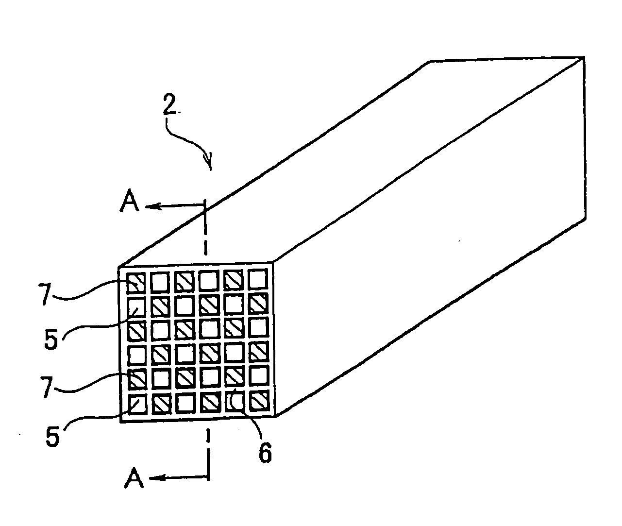
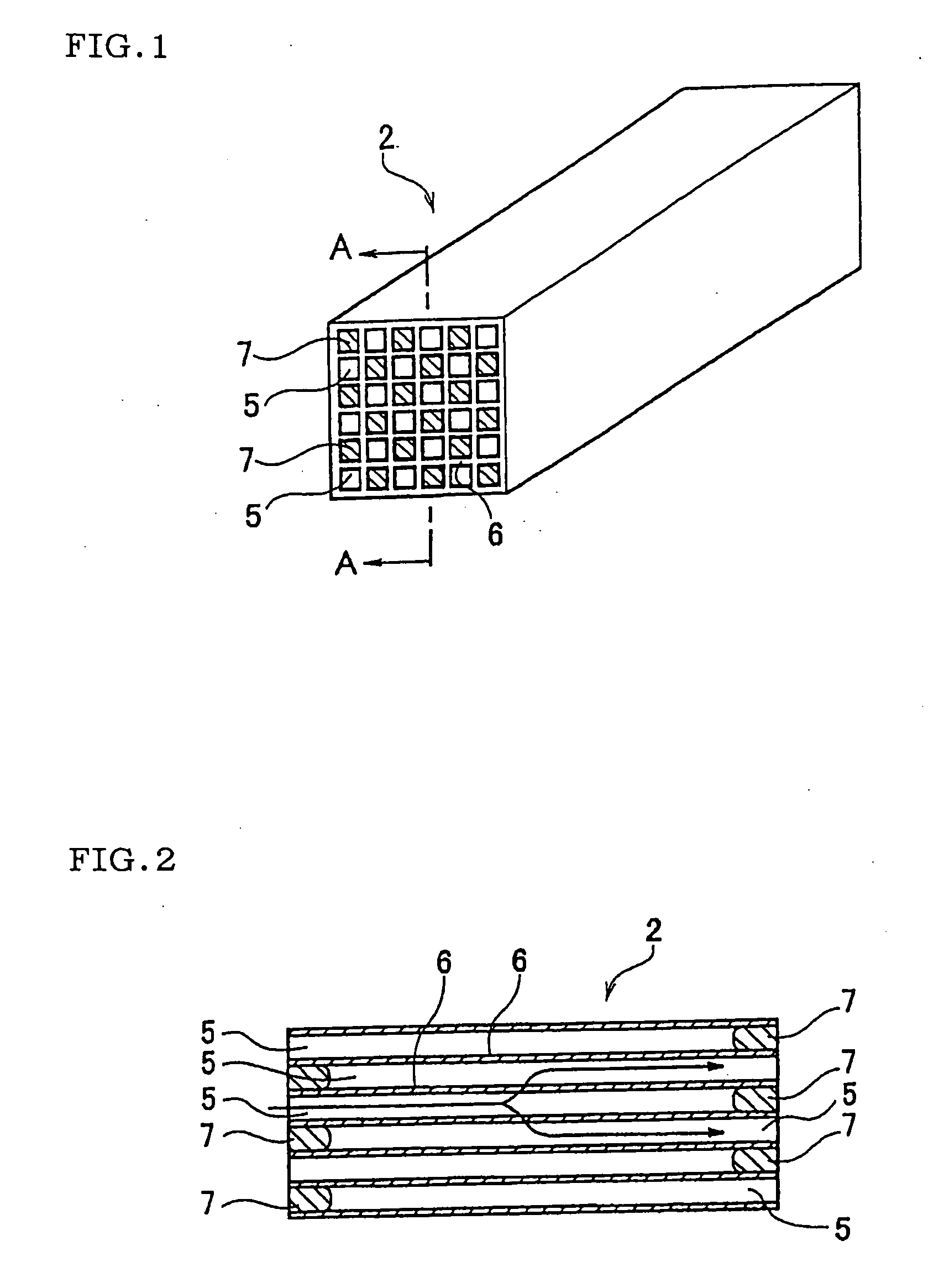
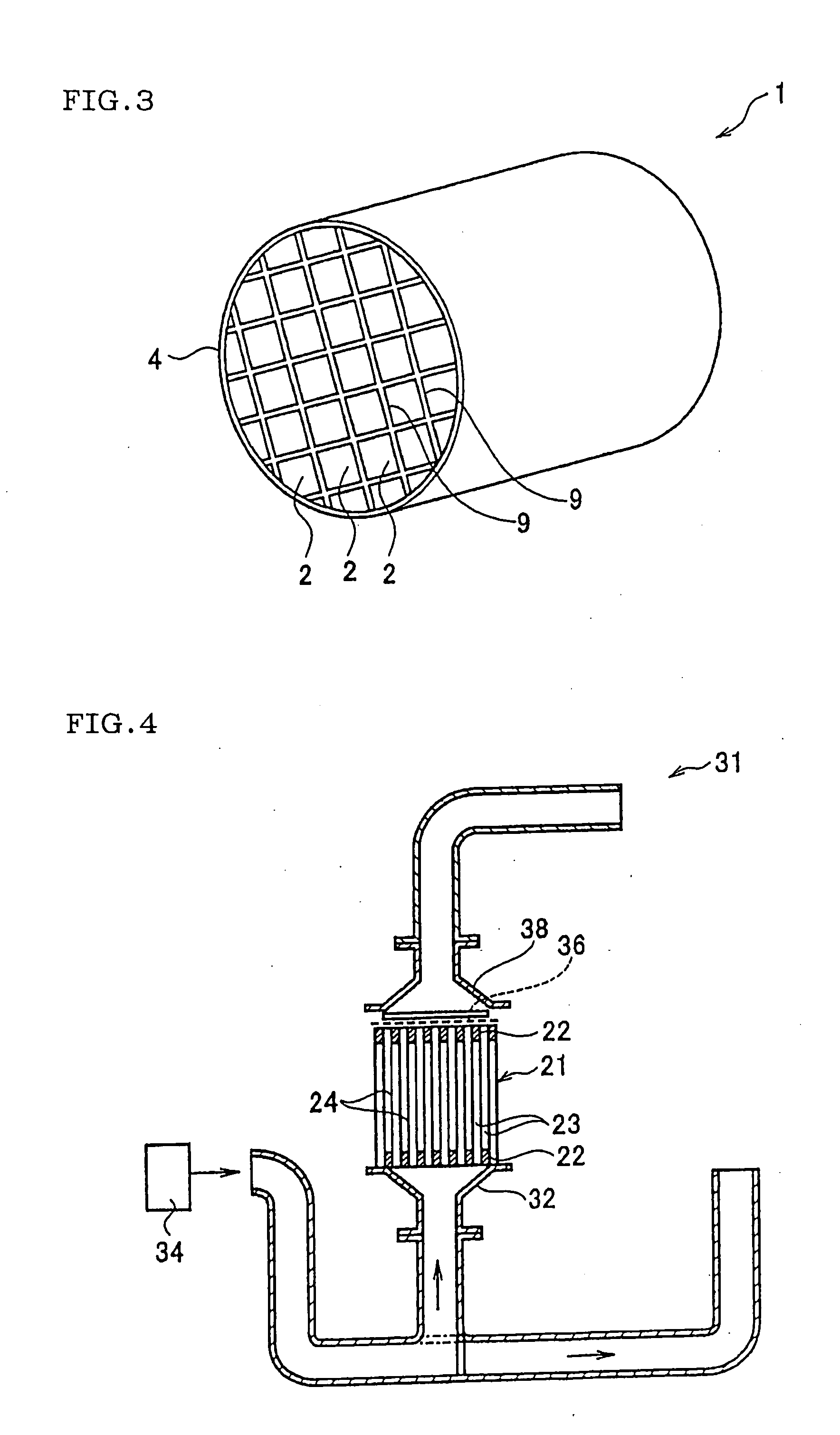
BACKGROUND OF THE INVENTION [0001] 1. Field of the Invention [0002] The present invention relates to a method of manufacturing a honeycomb structure for use in various types of filters or the like, and a method of manufacturing a honeycomb structure in which defects or deformations during forming can be reduced, and an amount of heat to be generated during degreasing can be reduced, so that it is possible to prevent cells from being cracked and improve yield. [0003] 2. Description of the Related Art [0004] Among various types of filters, for example, a diesel particulate filter (DPF) is a filter for use in trapping and removing particulates included in an exhaust gas from a diesel engine or the like, and the filter is incorporated in an exhaust system of the diesel engine when used. A filter such as the DPF is prepared by bonding a plurality of honeycomb structures (honeycomb segments), the honeycomb structure being as one unit (honeycomb segment). [0005]FIGS. 1 and 2 show the honey...

Claims


Application Information

Patent Timeline
Patent Type & Authority Applications(United States)
IPC IPC(8): C04B33/32B28B1/00C04B35/64B28B3/00
CPCB28B3/269C04B35/565C04B2235/3206C04B2235/3217C04B2235/3234C04B2235/3463C04B2235/77C04B2235/3481C04B2235/3826C04B2235/3873C04B2235/428C04B2235/48C04B2235/3472
Inventor KANEDA, ATSUSHIICHIKAWA, SHUICHI
Owner NGK INSULATORS LTD
Why Eureka
Try Eureka