Sheet flipping device

a technology of flipping device and sheet, which is applied in the direction of pile receiver, thin material handling, article delivery, etc., can solve the problems of less orderly stacking or even a device which becomes blocked

Active Publication Date: 2011-06-21
OCE TECH
View PDF8 Cites 0 Cited by
  • Summary
  • Abstract
  • Description
  • Claims
  • Application Information

AI Technical Summary

Benefits of technology

[0005]It is observed that the implementation of such a discharge element, which is arranged adjacent to the flipping volume, surprisingly increases the reliability of the flipping device as a result of better roll out of flipped sheets. Even without any physical contact between the discharge elements and the flipping sheets, the roll out of sheets, even of very floppy sheets, improves significantly.
[0006]In another embodiment of the device according to the present invention the multiple electrodes each have a sharp end pointing towards the flipping volume. It has been observed that sharp endings which point towards the flipping volume further increase the reliability of the sheet flipping device by further decreasing the risk of an erroneous roll out of a flipping sheet.
[0008]In another embodiment of the device according to the present invention, the discharge element is electrically connected to earth potential. It has been observed that a connection to earth of the discharge element reduces the risk of collapsing sheets during roll out after or during flipping.
[0009]In another embodiment of the device according to the present invention, the multiple electrodes comprise pin-electrodes. Pin-electrodes are usually relatively stiff with respect to flipping sheets. Discharge elements that are provided with pin-electrodes adjacent to the flipping volume have a positive influence on the reliability of the flipping device. The construction of pin-electrodes can be cost-efficient as they may be constructed from a single workpiece by milling, e.g., stainless steel or any other electrically conductive material or material with an electrically conductive surface.
[0010]In an embodiment of the device according to the present invention, each of said multiple electrodes comprise a fiber organ provided with a conductive outer surface. The fibre organ provides a flexible base for the electrically conductive outer surface. The fibre does not need to be electrically conductive itself. The mechanical flexibility of this type of electrode provides additional flexibility in the positioning of the discharge element with respect to handling different sheet sizes. Although it is preferred to arrange the discharge elements such that the end-portions are positioned just outside of the flipping volume, this type of mechanical flexible electrode does not disturb the formation of a straight stack when the end-portions are positioned slightly inside the flipping volume. If a sheet touches a small portion of such electrode it will flex automatically and continue its flipping movement almost undisturbed. The electrically conductive outer surface may comprise carbon or any other suitable conductive material.
[0011]In another embodiment of the device according to the present invention, the discharge element is moveably arranged, such that the lateral position with respect to the sheet is adaptable. By enabling a laterally adaptable positioning of the discharge element, in particular, the end-portions of the electrodes thereon, a variety of sheet sizes may be handled. It is preferred to arrange the end-portions of the electrodes just outside of the flipping volume in order not to disturb the flipping sheets' movement and to be close enough to function efficiently.

Problems solved by technology

However, it is a disadvantage of this known device that certain types of sheets, in particular floppy sheets with low stiffness in the direction of rotation, do not roll out correctly onto the receiving member, resulting in a less orderly stack or even a device which becomes blocked because of paper jams.

Method used


Image

  • Sheet flipping device
  • Sheet flipping device
  • Sheet flipping device

Examples


Embodiment Construction

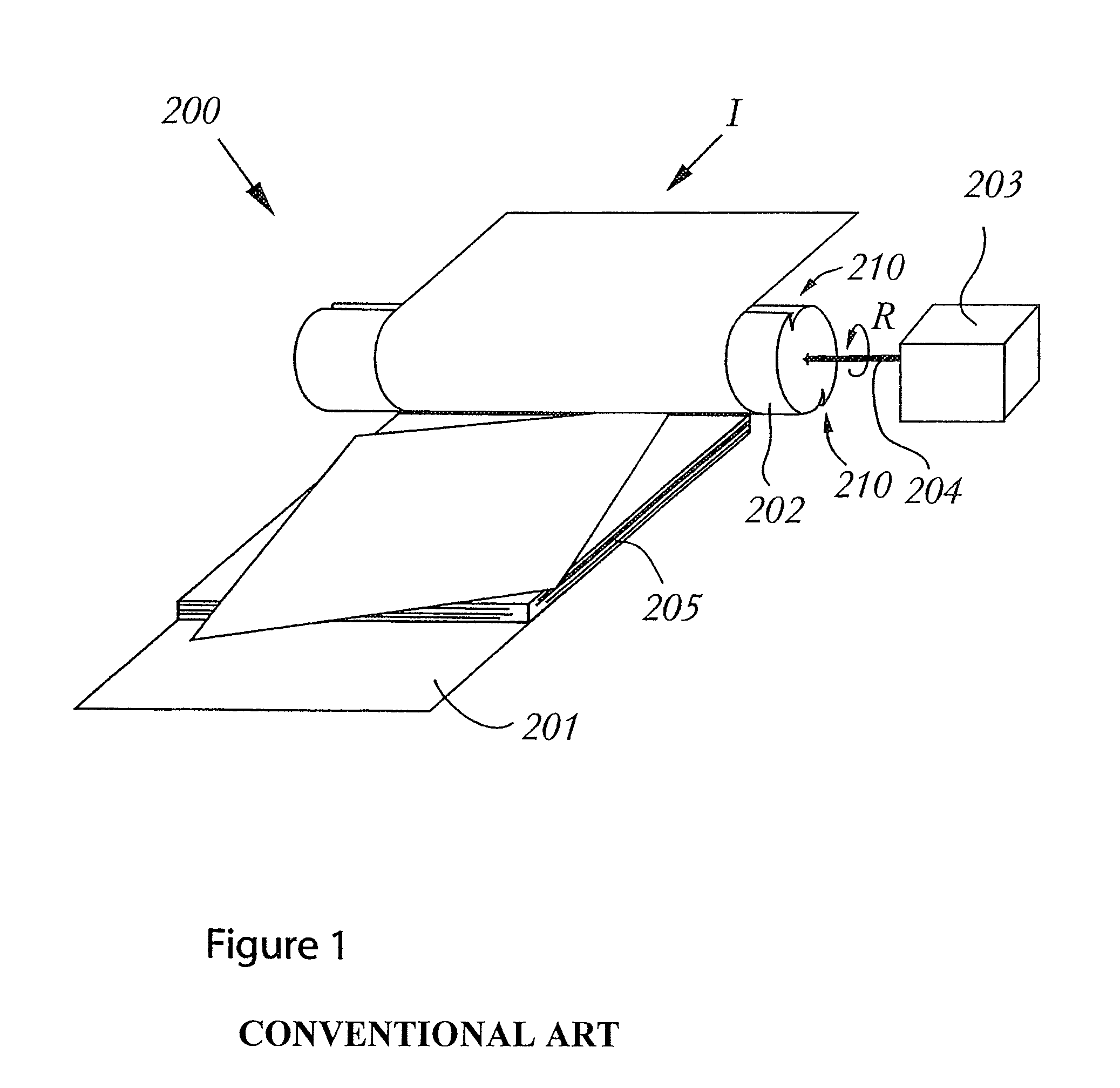
[0021]FIG. 1 is a schematic perspective view showing a sheet stacking device containing a flipping device. This sheet stacking device 200 comprises a receiving member 201 for receiving sheets to form a stack of sheets 205. The sheet stacking device further includes a rotatable flipping element, such as a flipping wheel 202. This flipping wheel has two slits 210 arranged along its circumference. These slits 210 are devised such that sheets which are fed towards the flipping wheel 202 in the input direction I are at least partly received by the slits 210. The flipping wheel 202 is rotatably driven by means of drive motor 203 and a coupled drive shaft 204. By rotating the flipping wheel 202 in rotational direction R, the sheets are flipped over and arranged on top of the receiving member 201 or a previously formed stack 205. The sheet stacking device has a relative high degree of erroneous formed stacks.

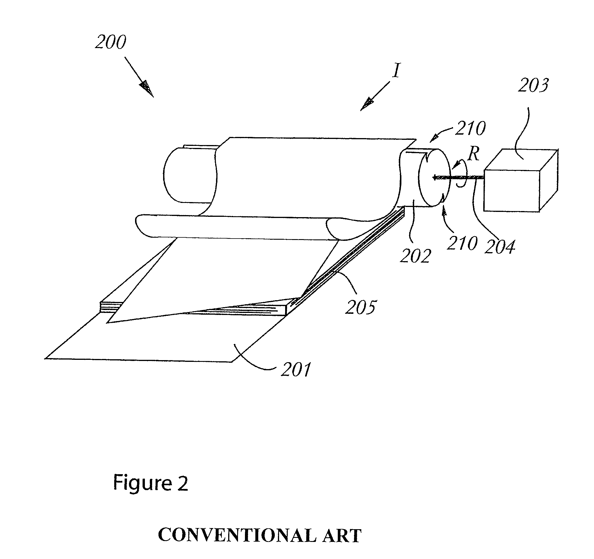
[0022]FIG. 2 shows a problem during operation of the sheet stacking device resultin...


PUM

PropertyMeasurementUnit
angleaaaaaaaaaa
top angleaaaaaaaaaa
top anglesaaaaaaaaaa

Abstract

A sheet flipping device including a receiving member for receiving a sheet, a flipping volume defined by the flipping movement of the sheet when in operation, a flipping element for flipping the sheet around an axis of rotation within the flipping volume onto the receiving member, and a discharge element arranged adjacent to said flipping volume, the discharge element having a base extending in a direction substantially perpendicular to the direction of the axis of rotation and having multiple electrodes with an end portion extending in a direction towards the flipping volume. The sheet flipping device is useable in a sheet stacking device and an image reproduction apparatus.

Description

[0001]This application claims priority from European Patent Applications No. 06125206.0 filed on Dec. 1, 2006 and No. 06126132.7 filed on Dec. 14, 2006, the entire contents of each being hereby incorporated by reference.[0002]The present invention relates to a sheet flipping device, comprising a receiving member for receiving a sheet, a flipping volume being the volume which, in operation, is defined by the flipping movement of the sheet, and a flipping element for flipping the sheet around an axis of rotation within the flipping volume onto the receiving member. The present invention also relates to a sheet stacking device and an image reproduction apparatus which utilizes the sheet flipping device.[0003]A device of this kind is described in FR 2 760 733. The device uses a flipping wheel to stack sheets on a receiving member in a flipped orientation. The flipping wheel comprises slits at its circumference to accommodate portions of a sheet. An abutment is provided to release the sh...

Claims


Application Information

Patent Timeline
Patent Type & Authority Patents(United States)
IPC IPC(8): B65H29/00
CPCB65H29/40B65H29/52B65H2404/652B65H2301/5132B65H2301/33214
Inventor DINNISSEN, JOHANNES H. A.
Owner OCE TECH
Why Eureka
Try Eureka