Eureka AIR delivers breakthrough ideas for toughest innovation challenges, trusted by R&D personnel around the world.

Auto ranging system and method for analog signal

a technology of analog signal and auto ranging, which is applied in the field of electronic and sensor, can solve the problems of insufficient resolution for some applications, inconvenient implementation, and inability to achieve the speed and performance of high-resolution a/d converters, and achieve the effect of not taking up extra space and being convenient to implemen

Inactive Publication Date: 2011-06-21
ENTEGRIS INC
View PDF30 Cites 7 Cited by
  • Summary
  • Abstract
  • Description
  • Claims
  • Application Information

AI Technical Summary

Benefits of technology

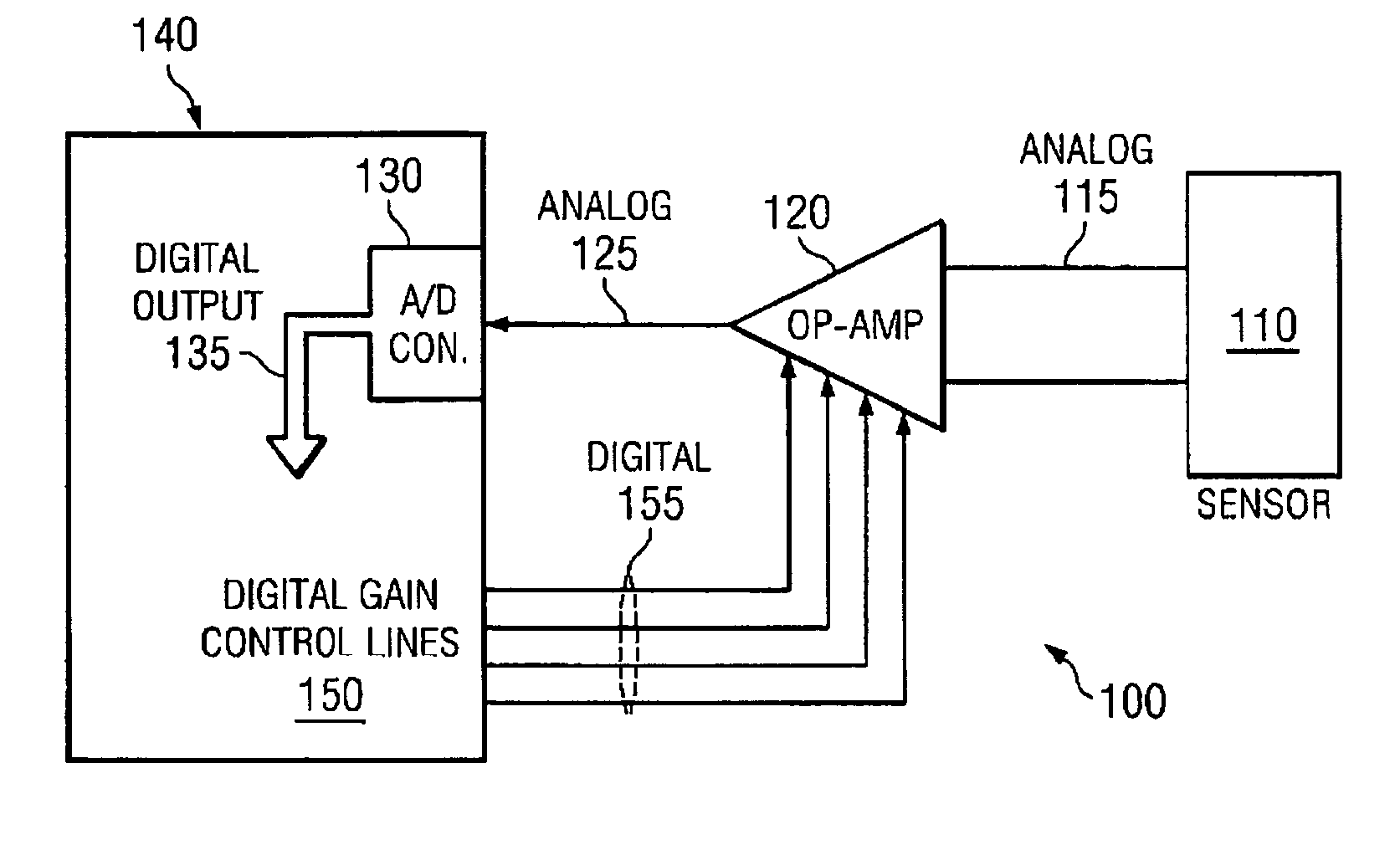
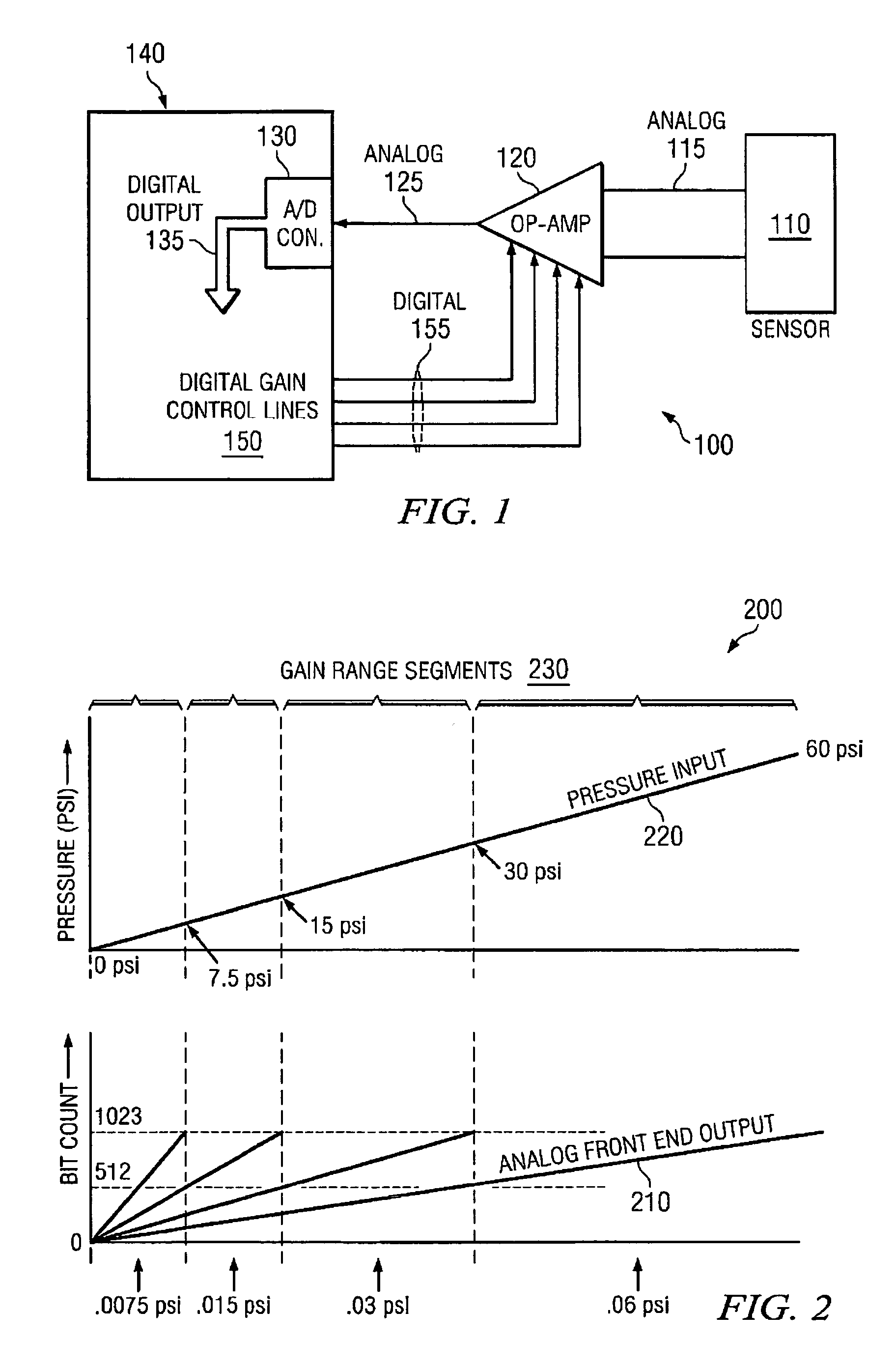
[0024]In some embodiments, the microprocessor can be configured to choose a gain that attempts to keep the output from the A / D converter in the top half of its range. In this way, the gains for the operational amplifier can be very precise. This is one advantage of the invention which can be further quantified. The precise control of the gains by the microprocessor makes calibration of the circuit optional.
[0025]Another advantage of the invention is that it eliminates the need for additional circuits and hardware components typically required for autoranging (e.g., comparator circuits, additional autoranging A / D converters, etc.). Yet another advantage of the invention is that the modification is mostly done on the processor. Thus, embodiments of the invention can be readily implemented and do not take up extra space.

Problems solved by technology

Conventional A / D converters, such as those which are typically packaged with microprocessors, cannot achieve the speed and performance of high-resolution A / D converters, which are typically integrated with external hardware and / or additional circuitry.
One problem is that they may not provide enough resolution for some applications.
However, the majority of the built-in A / D converters can only provide 8-10 bits resolution, which makes them inadequate for certain applications, particularly at the lower end of the scale.

Method used


Image

  • Auto ranging system and method for analog signal
  • Auto ranging system and method for analog signal
  • Auto ranging system and method for analog signal

Examples


Embodiment Construction

[0034]Most of the microprocessors today come with A / D converters, most of which are 8- or 10-bit A / D converters. Without any modification, these built-in A / D converters have limited applications and are generally inadequate for higher resolution applications such as flow control in a pump system utilized in a semiconductor manufacturing process. In prior auto ranging systems, additional hardware is required for high resolution applications. Typically, the added hardware is external to the A / D converter. Embodiments of the invention disclosed herein can utilize a low cost A / D converter (e.g., one comes with the purchase of a single chip microcontroller) in a manner that allows it to perform better (e.g., increased resolution) with minimal or no additional hardware, thus providing significant savings in cost and physical space.

[0035]Unlike prior systems in which external comparator(s), A / D converter(s), feedback circuit(s), and / or sensor(s) are used to control signals coming into the ...


PUM


Abstract

Disclosed herein are embodiments of an auto ranging system and method for an analog signal. A microprocessor is configured to digitally control the programmable gains of an operational amplifier based on the digital output of an A / D converter which may reside on or packaged along with the microprocessor. The amplifier receives a raw analog signal from a sensor and provides an amplified analog signal to the A / D converter. The gain of the amplifier generally corresponds to some range of the sensor signal. The A / D converter outputs a number of bits representative of the input signal. A microprocessor which is configured to digitally control the programmable gains of the amplifier receives and examines the output from the A / D converter and automatically adjusts the gain of the amplifier accordingly and as needed to keep or maintain the output from the A / D converter in a predetermined range.

Description

CROSS-REFERENCE TO RELATED APPLICATIONS[0001]This application claims priority from PCT / US07 / 17805, entitled “AUTO RANGING SYSTEM AND METHOD FOR AN ANALOG SIGNAL,” filed Aug. 10, 2007, which in turn claims priority from U.S. Provisional Patent Application No. 60 / 837,051, entitled “AUTO RANGING SYSTEM AND METHOD FOR AN ANALOG SIGNAL,” filed Aug. 11, 2006, by inventor Robert F. McLoughlin, both of which are hereby fully incorporated by reference herein for all purposes.TECHNICAL FIELD OF THE INVENTION[0002]Embodiments of the invention relate generally to electronics and sensors and more particularly to systems and methods for changing the gain of an input amplifier to an analog-to-digital (“A / D”) converter.BACKGROUND OF THE INVENTION[0003]In many electronic systems, a sensor (e.g., a pressure sensor) outputs a signal having a voltage representative of a condition (e.g., a pressure). An amplifier multiplies the signal by a gain to create an input signal for the A / D converter. Prior syst...

Claims


Application Information

Patent Timeline
Patent Type & Authority Patents(United States)
IPC IPC(8): H03M1/00
CPCH03M1/183H03G3/001H03G3/30H03M1/1235
Inventor MCLOUGHLIN, ROBERT F.
Owner ENTEGRIS INC
Why Eureka
Eureka Blog
Learn More