Heat-dissipation module and electronic device using the same

a technology of heat dissipation module and electronic device, which is applied in the direction of lighting, heating apparatus, and electrical equipment casings/cabinets/drawers, etc., can solve the problems of reducing heat dissipation efficiency, ineffective utilization of fan efficiency, and inability to effectively dissipate heat from the internal elements or chips of electronic products, so as to improve heat dissipation efficiency and heat dissipation. , the effect of increasing

Inactive Publication Date: 2011-06-21
QUANTA COMPUTER INC
View PDF10 Cites 29 Cited by
  • Summary
  • Abstract
  • Description
  • Claims
  • Application Information

AI Technical Summary

Benefits of technology

[0011]In the present invention, one end of each heat pipe is in contact with one heat source, and heat generated by the heat source is transferred to different sets of heat fins via several heat pipes, so as to dissipate heat. By forming a continuous heat-exchange cycle between the two ends of each heat pipe, the heat-dissipation efficiency is increased, the heat-exchange capability is improved, and the efficiency of the fan is fully utilized. Moreover, the phenomenon of partial failure of the heat pipe is prevented and the operation stability of the heat source is assured.

Problems solved by technology

Therefore, how to effectively dissipate heat from the internal elements or chips of electronic products has become an important issue, especially in the trend of increasing internal integration, miniaturizing and light-weight of electronic products.
However, in a circumstance that only the CPU is fully operated and generates a significant amount of heat than other heat sources, the fan of the heat dissipation module is fully operated to take the heat away from the CPU.
As a result, the efficiency of the fan merely partly applies to where it is really needed; in other words, the efficiency of the fan is unable to be utilized effectively.
However, when one heat source contacting with one end of the heat pipe develops a large amount of heat, the heat will spread to the other heat source contacting with the other end of the heat pipe.
Consequently, heat will aggregate in the other heat source, making it overheated.
In a worse case, a phenomenon of partial failure of the heat pipe occurs and the heat dissipation efficiency is lowered and further deteriorating the stability of chip operation.

Method used


Image

  • Heat-dissipation module and electronic device using the same
  • Heat-dissipation module and electronic device using the same
  • Heat-dissipation module and electronic device using the same

Examples


Embodiment Construction

[0019]Reference will now be made in detail to the present embodiments of the invention, examples of which are illustrated in the accompanying drawings.

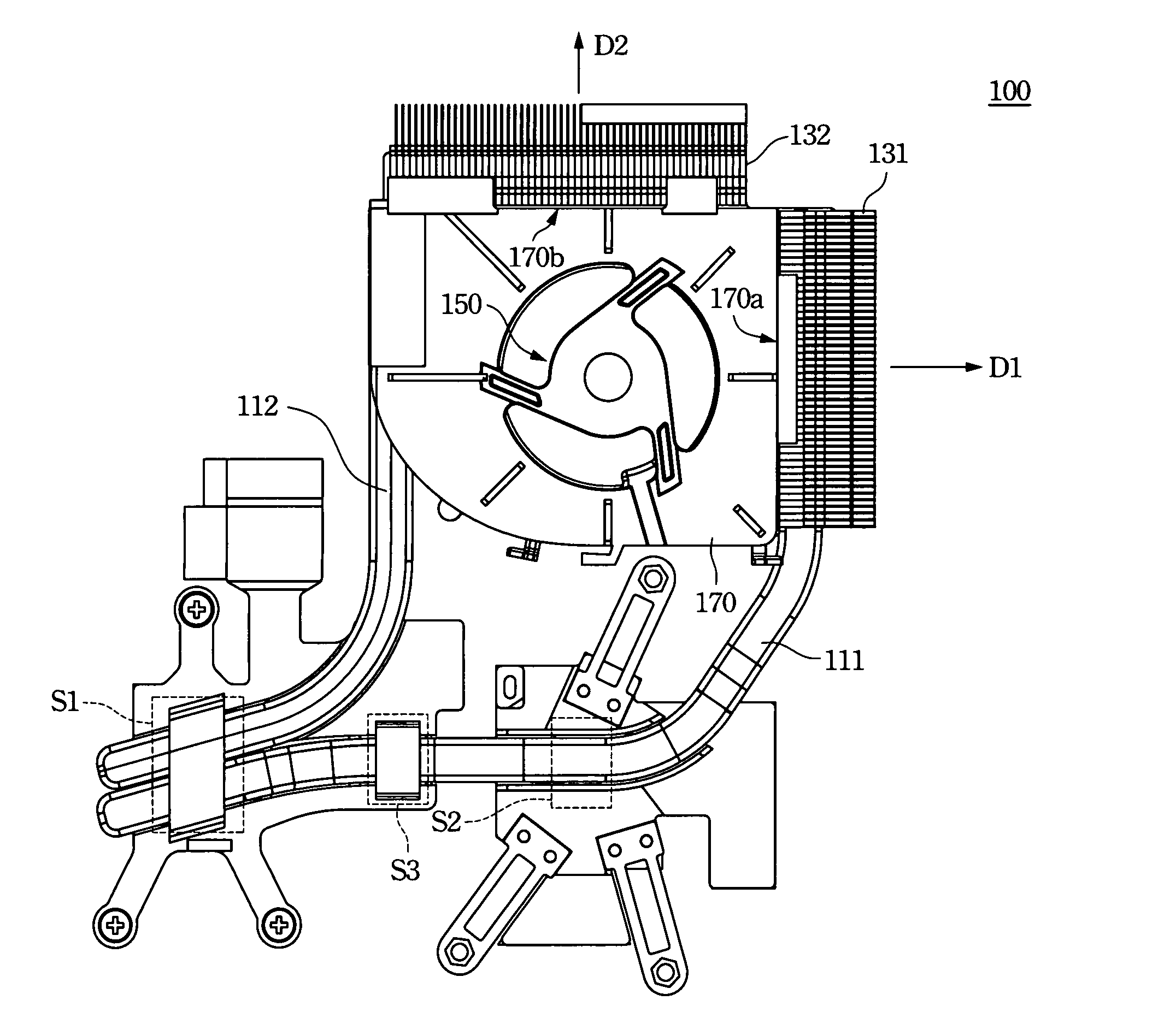
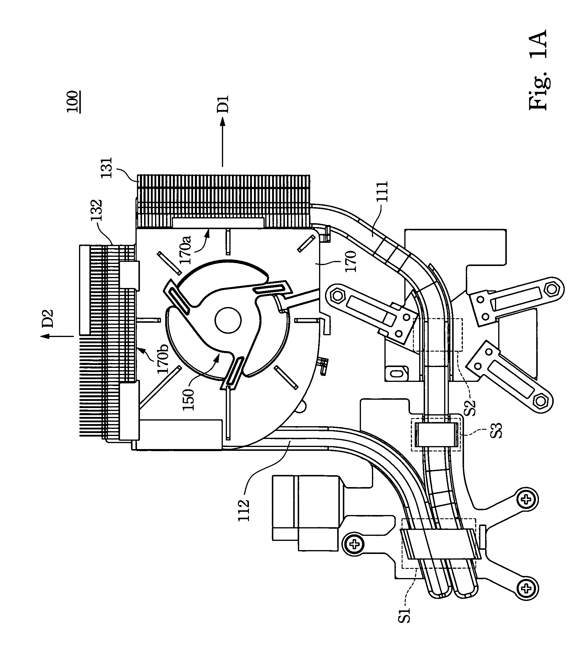
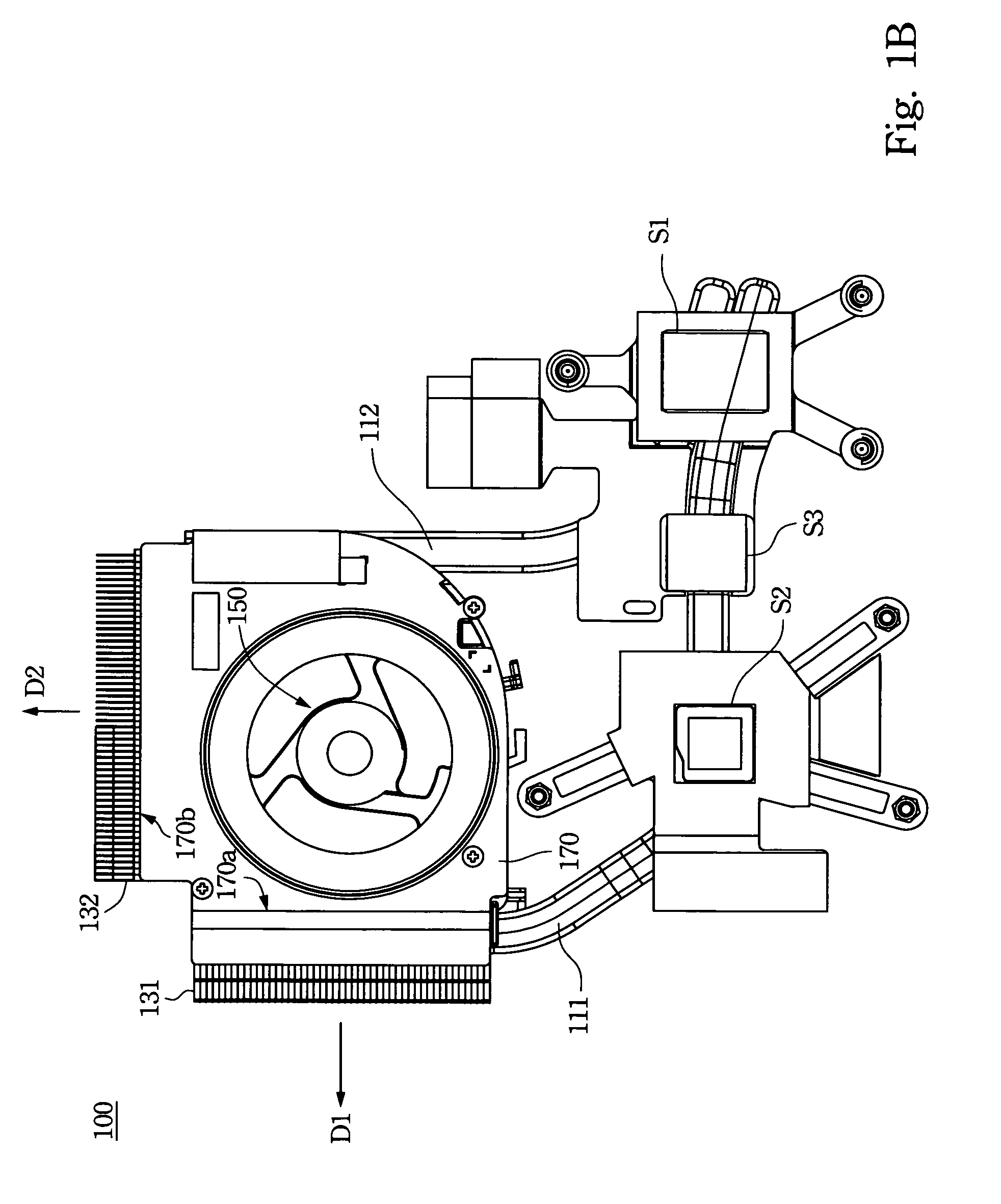
[0020]In the present embodiment of the invention, more than one heat pipes are used to dissipate heat from one heat source. A continuous heat-exchange cycle is formed between two ends of each heat pipe, and therefore the issue of heat aggregation at the heat source causing partial failure of the heat pipe can be prevented. In addition, single heat pipe can be further in contact with more than one heat sources to increase heat-dissipation efficiency and capability of the heat-dissipation module. Please refer to FIG. 1A and FIG. 1B at the same time. The two figures respectively illustrate a front-side view and a back-side view of a heat-dissipation module according to one embodiment of the invention.

[0021]The heat-dissipation module 100 mainly includes a first heat pipe 111, a second heat pipe 112, a first set of heat fins 131, a second...


PUM


Abstract

A heat-dissipation module and an electronic device including a first heat source and the heat-dissipation module are provided. The heat-dissipation module includes a first heat pipe, a second heat pipe, a first set of heat fins, a second set of heat fins and a fan. One end of the first heat pipe and one end of the second heat pipe are respectively in contact with the first heat source. The first set of heat fins and the second set of heat fins are, respectively, in contact with the other end of the first heat pipe and the other end of the second heat pipe. Heat generated by the first heat source is transferred to the two sets of heat fins through the first and the second heat pipes. The fan is used for providing an air-flow blowing toward the two sets of heat fins to dissipate heat.

Description

RELATED APPLICATIONS[0001]This application claims priority to Taiwan Application Serial Number 98201622, filed on Feb. 3, 2009, which is herein incorporated by reference.BACKGROUND[0002]1. Field of Invention[0003]The present invention relates to a heat-dissipation module and an electronic device using the same. More particularly, the present invention relates to a heat-dissipation module having more than one heat pipes and an electronic device using the same.[0004]2. Description of Related Art[0005]Along with the development of semiconductor technology, the fabricating process keeps scaling down, the number of transistors per unit area multiplies, and the efficiency of chips progresses rapidly; however, the unit heat generated by chips also increases significantly. Therefore, how to effectively dissipate heat from the internal elements or chips of electronic products has become an important issue, especially in the trend of increasing internal integration, miniaturizing and light-we...

Claims


Application Information

Patent Timeline
Patent Type & Authority Patents(United States)
IPC IPC(8): H05K7/20F28D15/00
CPCF28D15/0266G06F1/203F28F1/24
Inventor HUANG, LUNG-CHILIN, KUANG-HUAHSU, FENG-LIN
Owner QUANTA COMPUTER INC
Why Eureka
Try Eureka