
Charging device and image forming device using same

a charging device and image forming technology, applied in the direction of electrographic process equipment, instruments, corona discharge, etc., can solve the problems of ozone pollution, ozone filtering adds to running costs, ozone pollution is harmful to humans, etc., and achieves the effect of reducing ozone production

Inactive Publication Date: 2011-06-28
SHARP KK
View PDF13 Cites 9 Cited by
  • Summary
  • Abstract
  • Description
  • Claims
  • Application Information

AI Technical Summary

Benefits of technology

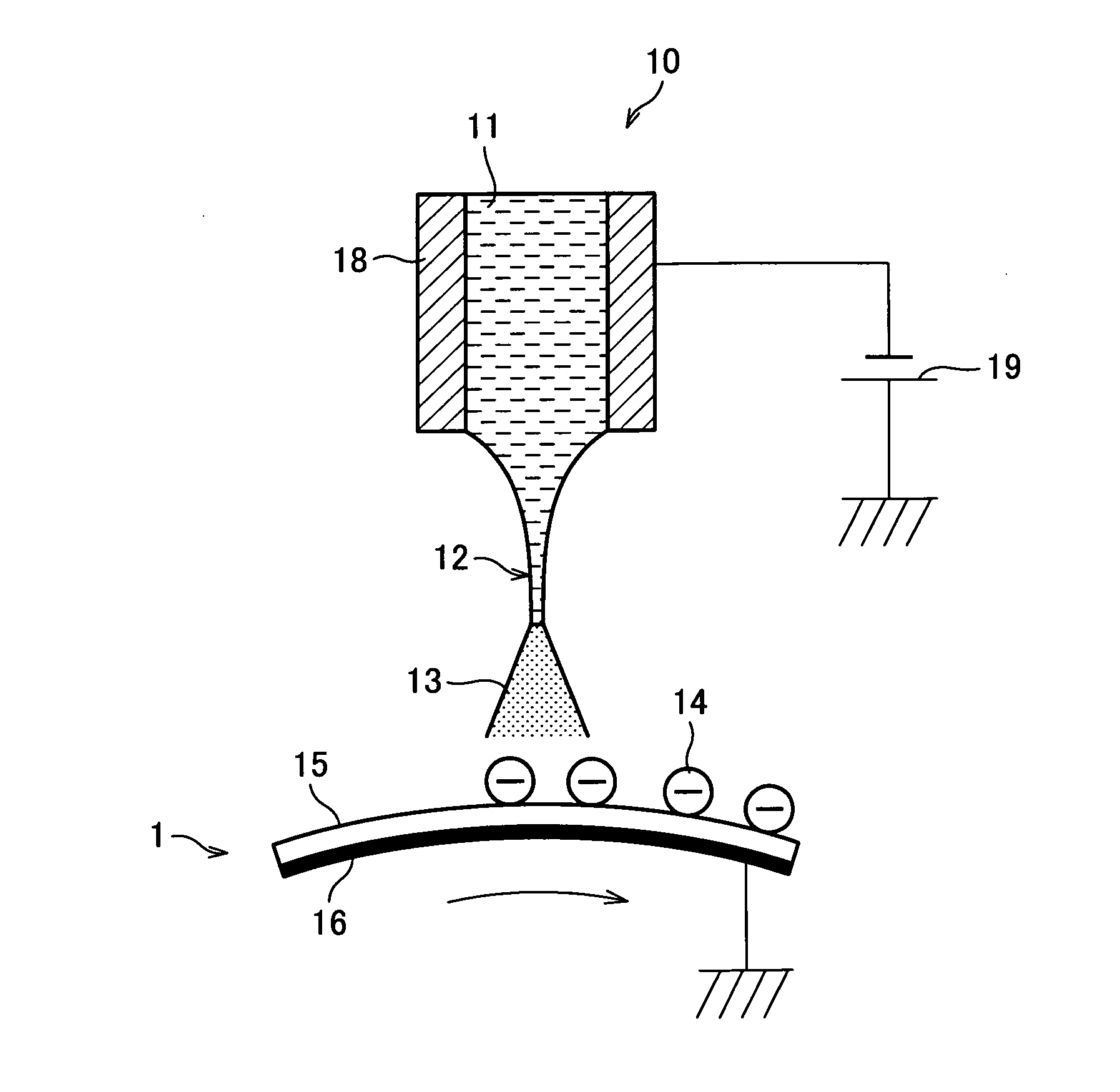
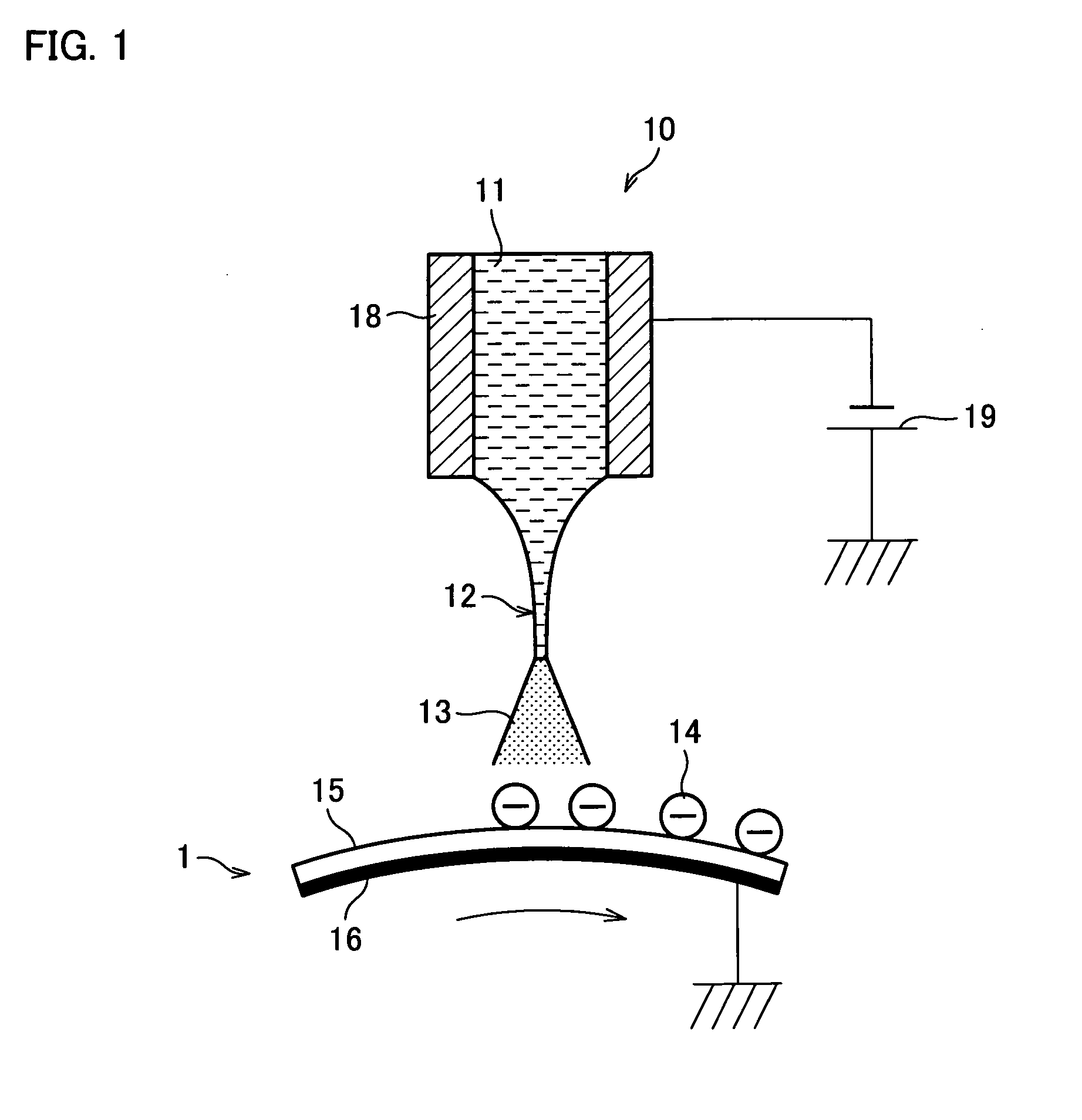
The present invention provides a charging device and an image forming device that can reduce ozone production while preventing degradation or wearing of the charging device and the electrostatic latent image carrier. The charging device uses electrospray means to induce electrospraying through application of a voltage to an incoming liquid, resulting in charged liquid droplets that can be used to charge the electrostatic latent image carrier. This charging method does not involve corona discharge, reducing the harmful effects of ozone on human health. The image forming device includes the charging device and an electrostatic latent image carrier, resulting in less ozone formation and less friction between the device and the carrier.

Problems solved by technology

A problem therefore arises that the scorotron chargers produce a large quantity of ozone.
Ozone is harmful to humans.
The use of the ozone filter, however, leads to other problems: the oxidizing effect of ozone adversely affects internal components, and the replacement of the ozone filter adds to running cost.
The charging device of a roller charging scheme generates corona discharge on the surface of the electrostatic latent image carrier; the surface of the electrostatic latent image carrier and the charge roller may degrade or wear out.
Similar problems, the degradation and wearing of the charge brush, can occur in the charging device of a brush charging scheme.
That aggravates the problems and makes it more difficult to tweak the charging devices of these schemes for use in a high-speed image forming device.

Method used


Image

  • Charging device and image forming device using same
  • Charging device and image forming device using same
  • Charging device and image forming device using same

Examples


Embodiment Construction

[0054]The following will describe an embodiment of the present invention in reference to FIGS. 1 to 19.

[0055]The present embodiment will focus on electrophotographic digital copying machines as the image forming device that is in accordance with the present invention. This is not at all meant to be limiting the scope of the invention. The image forming device in accordance with the invention is applicable also, for example, to printers and facsimile machines provided that they operate based on electrophotographic principles.

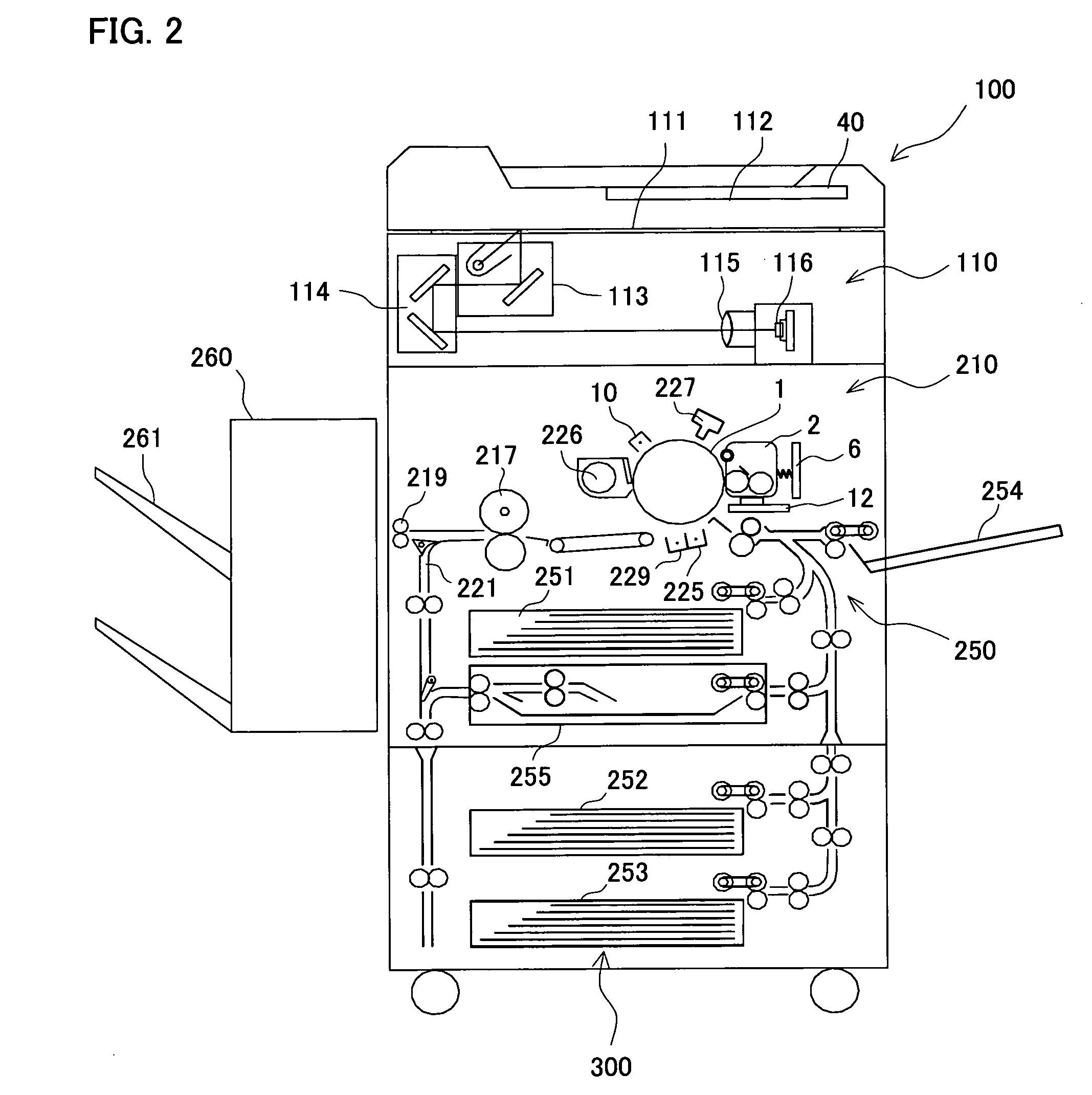
[0056]FIG. 2 is a cross-sectional view of a digital copying machine 100 incorporating a charging device 10 of the present embodiment. The digital copying machine 100 of the present embodiment, as illustrated in FIG. 2, includes an original image capture section 110, an image forming section 210, a paper feeding section 300, and a post-processing device 260.

[0057]The original image capture section 110 includes an original document platen 111 made of transparent gl...


PUM


Abstract

A charging device (10) includes electrospray means for inducing electrospraying through application of a voltage to an incoming liquid (11), in order to produce charged liquid droplets (13). The device (10) charges a photoreceptor drum (1) by means of the liquid droplets (13). Hence, the invention provides a charging device capable of reducing ozone production while preventing the charging device and the electrostatic latent image carrier from degrading or wearing out from friction between the device and the carrier and provides also an image forming device incorporating the charging device.

Description

TECHNICAL FIELD[0001]The present invention relates to charging devices which charge the surface of an electrostatic latent image carrier to form an electrophotographic image and also relates to image forming devices which incorporate such a charging device.BACKGROUND ART[0002]A corona charger has been used as a charging device for an electrostatic latent image carrier in a wide range of conventional electrophotographic image forming devices. The most common corona charger is of a scorotron type (hereinafter, “scorotron charger”) which is made up of a discharge electrode, an enclosure, and a grid electrode. The grid electrode, provided behind a discharge opening of the scorotron charger, is positioned to face the electrostatic latent image carrier, but so as to make no direct mechanical contact with the carrier. Ions are discharged at the surface of the electrostatic latent image carrier through the discharge opening to charge the surface of the electrostatic latent image carrier uni...

Claims


Application Information

Patent Timeline
Patent Type & Authority Patents(United States)
IPC IPC(8): G03G15/02
CPCG03G15/0291G03G15/0208
Inventor IWAMATSU, TADASHIKANDA, HIROFUMI
Owner SHARP KK
Learn More