Ozone generator

a generator and ozone technology, applied in the field of ozone generators, can solve the problems of lowering ozone production efficiency and ozone production efficiency, and achieve the effects of reducing the amount of humidified source gas in the discharge space, and reducing the amount of ozone production

Active Publication Date: 2015-10-01
NGK INSULATORS LTD
View PDF2 Cites 0 Cited by
  • Summary
  • Abstract
  • Description
  • Claims
  • Application Information

AI Technical Summary

Benefits of technology

[0024]In the feature [7] or [8], the electrode pairs are not located in positions to which a large amount of the humidified source gas is introduced. Therefore, the amount of the humidified source gas in the discharge space can be reduced. Furthermore, one side of the discharge surfaces of the electrode pairs is not brought into direct contact with the source gas, whereby the surface of one dielectric body can be maintained in a low-humidity state even when the water or OH molecules are adsorbed to the surface. Thus, the reduction of the ozone production amount can be decreased.
[0025][9] In the present invention, of the two electrodes, one electrode may be located on an upstream side of the source gas and another electrode may be located on a downstream side of the source gas, and a direction from the one electrode toward the other electrode may be inclined with respect to a supply direction of the source gas. In this case, one side of the discharge surfaces of the electrode pairs is not brought into direct contact with the source gas. Therefore, the surface of one dielectric body can be maintained in a low-humidity state even when the water or OH molecules are adsorbed to the surface. Thus, the reduction of the ozone production amount can be decreased.
[0026][10] It is preferred that the angle between the direction from the one electrode toward the other electrode and the supply direction of the source gas has an absolute value of 80° or less. In this case, one side of the discharge surfaces of the electrode pairs is not brought into direct contact with the source gas. Therefore, the surface of one dielectric body can be maintained in a low-humidity state even when the water or OH molecules are adsorbed to the surface. Thus, the reduction of the ozone production amount can be decreased.
[0027][11] It is preferred that an angle between the direction from the one electrode toward the other electrode and the supply direction of the source gas has an absolute value of 60° or less. In this case, the reduction of the source gas amount can be decreased between the two electrodes, one side of the electrode pair can be maintained in a low-humidity state, and the ozone production amount can be increased.
[0028][12] It is preferred that an angle between the direction from the one electrode toward the other electrode and the supply direction of the source gas has an absolute value of 10° or more. In this case, the reduction of the ozone production amount, due to lack of the source gas between the one electrode and the other electrode (in the discharge space), can be decreased.
[0029][13] It is preferred that an angle between the direction from the one electrode toward the other electrode and the supply direction of the source gas has an absolute value of 30° or more. In this case, the reduction of the source gas amount can be decreased between the two electrodes, one side of the electrode pair can be maintained in a low-humidity state, and the ozone production amount can be increased.

Problems solved by technology

However, the conventional ozone generators are disadvantageous in that the produced ozone is decomposed by a water molecule or an OH group (hydroxyl group), resulting in a lowered ozone production efficiency, in a high-humidity environment.
Furthermore, the ozone production efficiency is lowered with the operation time in a high-humidity environment disadvantageously.

Method used


Image

  • Ozone generator
  • Ozone generator
  • Ozone generator

Examples


first example

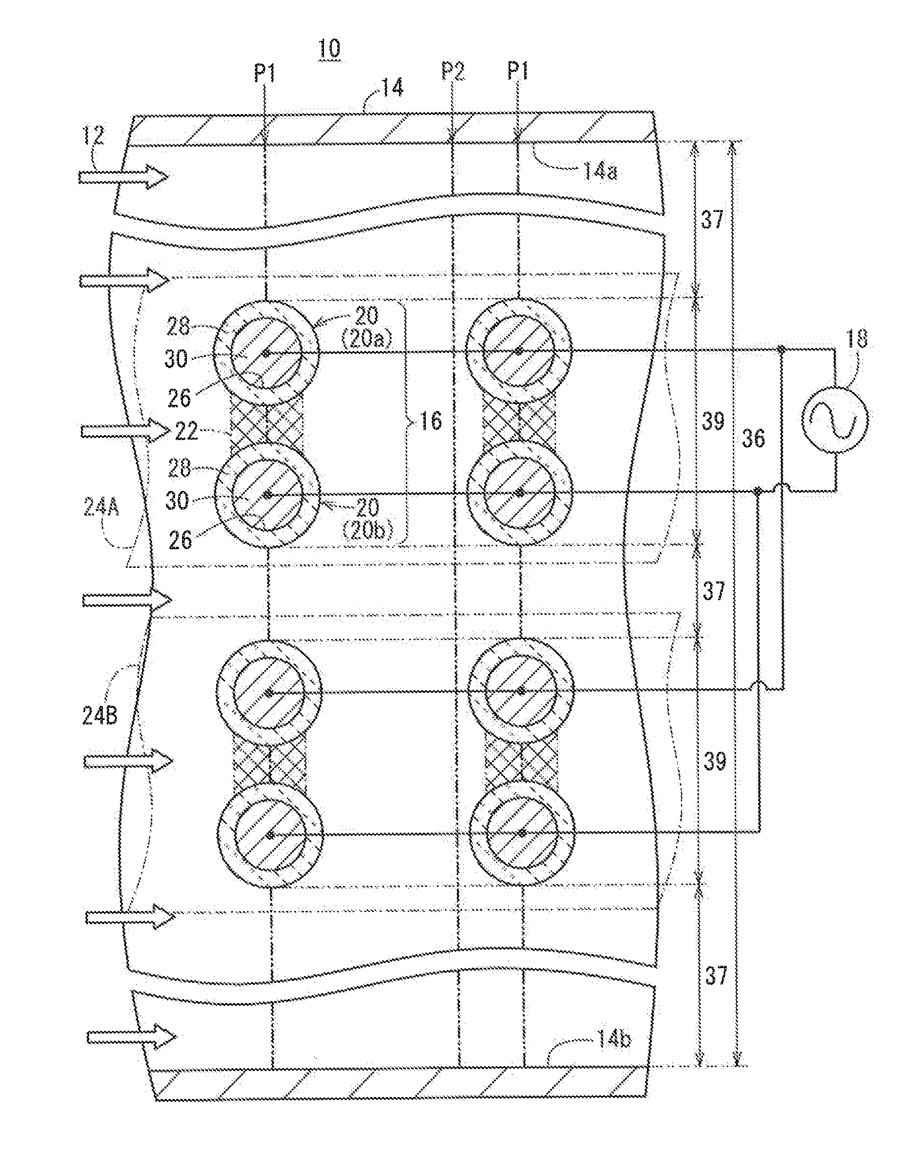
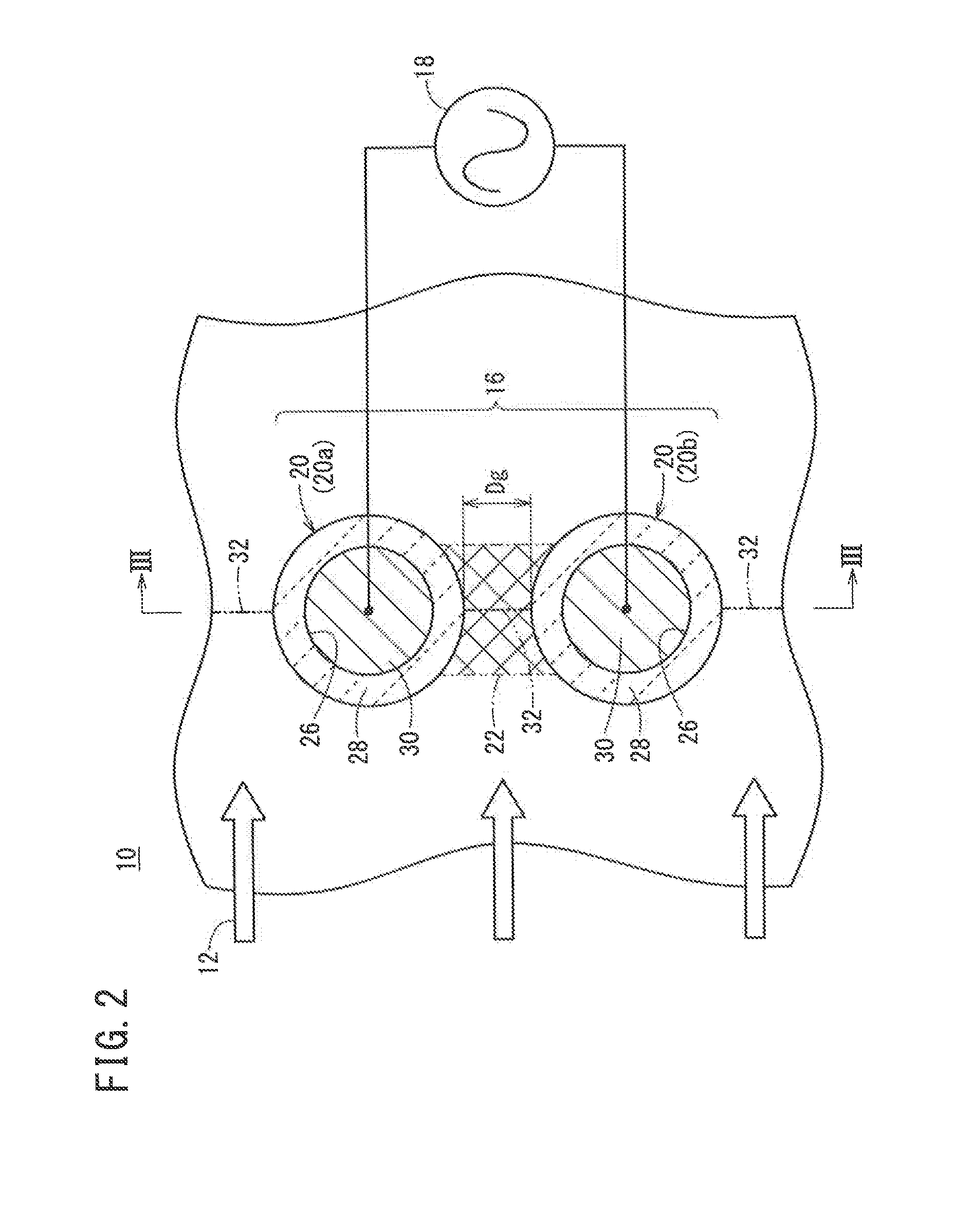
[0105]Changes in ozone production amount in samples 1 to 5 were evaluated under various supply flow rates of a source gas. In the samples, the dielectric body 28 was made of alumina and the conductive body 30 was made of copper in each electrode 20.

(Method for Measuring Ozone Production Amount)

[0106]In the measurement of the ozone production amount, an air (having an absolute humidity of 30 g / m3) was used as the source gas 12 under a gas pressure of 0.10 MPa.

[0107]The alternating-current power source 18 was used as a discharge power source for applying an alternating-current voltage with a voltage (amplitude A) of ±4 kV and a frequency f of 20 kHz.

[0108]The ozone concentration in the exhaust gas was measured using an ozone concentration meter EG-3000D (available from Ebara Jitsugyo Co., Ltd.) under the above conditions. The ozone production amount was obtained by multiplying the measured value by a supply flow rate.

[0109]The details of electrode structures in ozone generators of the...

second example

[0115]Ozone production amount changes of samples 6 to 9 were evaluated under various supply flow rates of a source gas. The ozone production amounts were obtained in the same manner as First Example.

[0116]The details of electrode structures in ozone generators of the samples 6 to 9 were as follows.

(Samples 6 and 7)

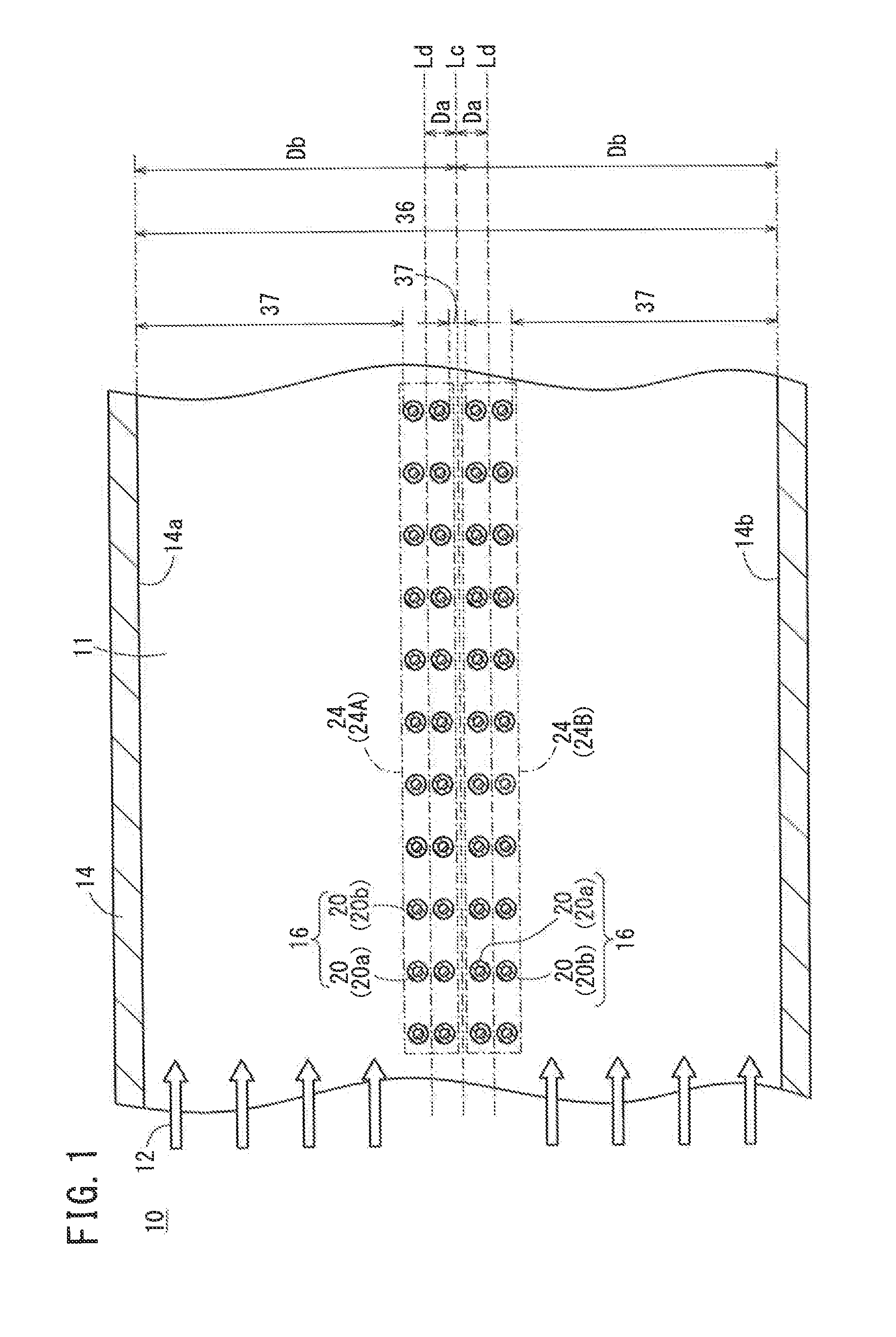
[0117]In the samples 6 and 7, the distances Da between the center line Lc of the internal cavity 11 and the center position Ld of the electrode pair column 24 were 2 mm and 5 mm, respectively, in the ozone generator 10 shown in FIG. 1. In the samples 6 and 7, the values obtained by subtracting the distance Da from the distance Db between the center line Lc of the internal cavity 11 and the inner wall of the housing 14 were 96 mm and 90 mm, respectively.

(Samples 8 and 9)

[0118]In the samples 8 and 9, the distances Da were 7.5 mm and 10 mm, respectively, in the ozone generator 10a of the first modification example shown in FIG. 5.

(Evaluation Result)

[0119]The evaluation result...


PUM

PropertyMeasurementUnit
distanceaaaaaaaaaa
distanceaaaaaaaaaa
angleaaaaaaaaaa

Abstract

An ozone generator includes a housing having an internal cavity and a plurality of electrode pairs located in the internal cavity. The electrode pairs each contain two electrodes arranged at a distance of a predetermined gap length, and a discharge space is formed between the two electrodes, whereby ozone is produced when a source gas flows at least between the two electrodes and a discharge is generated between the two electrodes. The ozone generator has a non-discharge portion in an arbitrary cross-section having a normal direction parallel to a main flow direction of the source gas in the internal cavity.

Description

CROSS-REFERENCE TO RELATED APPLICATION[0001]This application is based upon and claims the benefit of priority from Japanese Patent Application No. 2014-074618 filed on Mar. 31, 2014, the contents of which are incorporated herein by reference.BACKGROUND OF THE INVENTION[0002]1. Field of the Invention[0003]The present invention relates to an ozone generator for flowing a source gas between electrodes and generating a discharge between the electrodes, thereby producing ozone.[0004]2. Description of the Related Art[0005]An ozone generator is an apparatus capable of flowing an oxygen-containing gas such as air in a thermal non-equilibrium plasma to produce ozone. The thermal non-equilibrium plasma is generated utilizing a discharge provided by a discharge generating device. For example, the discharge generating device may be of a silent discharge type. For example, in this device, a high voltage of several to several tens kV is applied by a high-voltage alternating-current power source t...

Claims


Application Information

Patent Timeline
Patent Type & Authority Applications(United States)
IPC IPC(8): C01B13/11
CPCC01B13/115C01B13/11C01B2201/14C01B2201/22C01B2201/40C01B2201/62
Inventor KONDO, YOSHIMASAYOKOI, SHOJITERAZAWA, TATSUYATAKASE, NAOYA
Owner NGK INSULATORS LTD
Why Eureka
Try Eureka