Method and apparatus for limiting domain name server transaction bandwidth

a domain name server and bandwidth limitation technology, applied in the field of domain name server transactions, can solve the problem of not being able to block dns transactions, and achieve the effect of reducing the risk of malicious interception of dns transactions

Active Publication Date: 2011-06-28
CISCO TECH INC
View PDF17 Cites 24 Cited by
  • Summary
  • Abstract
  • Description
  • Claims
  • Application Information

AI Technical Summary

Benefits of technology

[0007]The DNS transaction can be further understood with reference to FIG. 3 which is a flow diagram showing the steps involved and FIG. 4 which is a schematic diagram of a DNS request. At step 300 the user device sends a DNS request packet and at step 302 the SSG receives a packet and recognizes it as a DNS request. All DNS requests are received on UDP port 53 allowing simple recognition by the SSG. At step 304 the SSG redirects the DNS request to the DNS proxy 114. As is well known, the DNS proxy sends out a proxy DNS request with itself as source address such that DNS responses are received at it. This reduces the risk of m

Problems solved by technology

In many instances authorization is not required for DNS transactions such that an unauthorized user can package an IP ses

Method used


Image

  • Method and apparatus for limiting domain name server transaction bandwidth
  • Method and apparatus for limiting domain name server transaction bandwidth
  • Method and apparatus for limiting domain name server transaction bandwidth

Examples


Embodiment Construction

[0022]A method and apparatus for limiting DNS transaction bandwidth is described. In the following description, for the purposes of explanation, numerous specific details are set forth in order to provide a thorough understanding of the present invention. It will be apparent, however, to one skilled in the art that the present invention may be practiced without these specific details. In other instances, well-known structures and devices are shown in block diagram form in order to avoid unnecessarily obscuring the present invention.

[0023]Embodiments are described herein according to the following outline:

[0024]1.0 General Overview

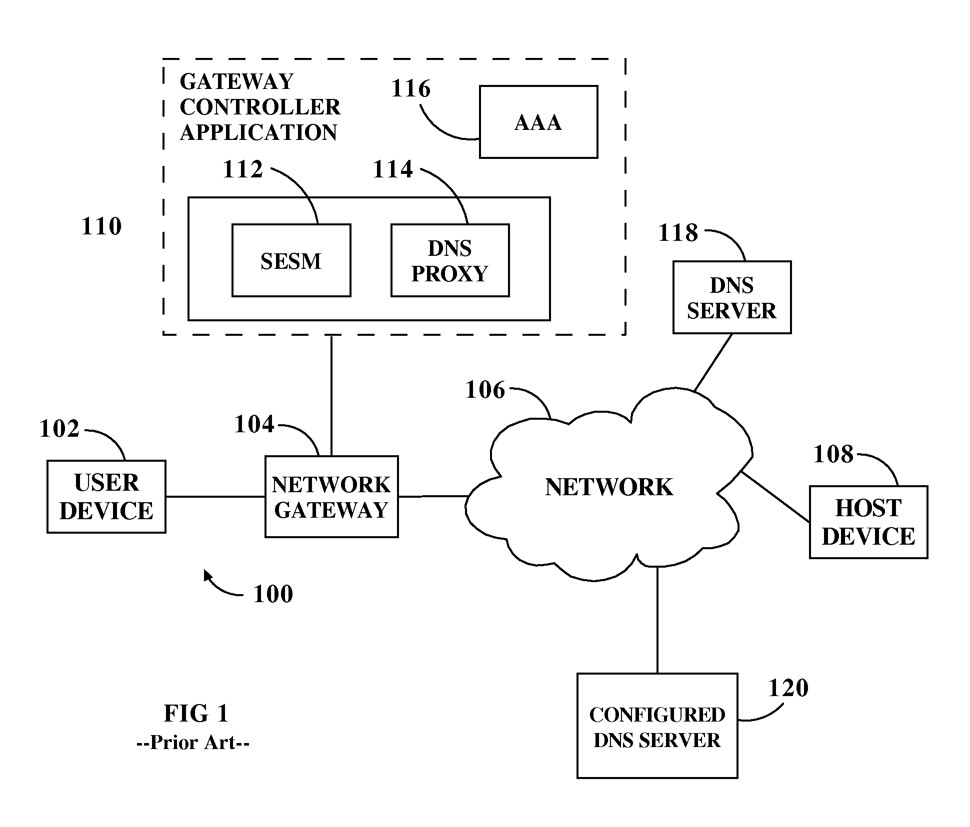
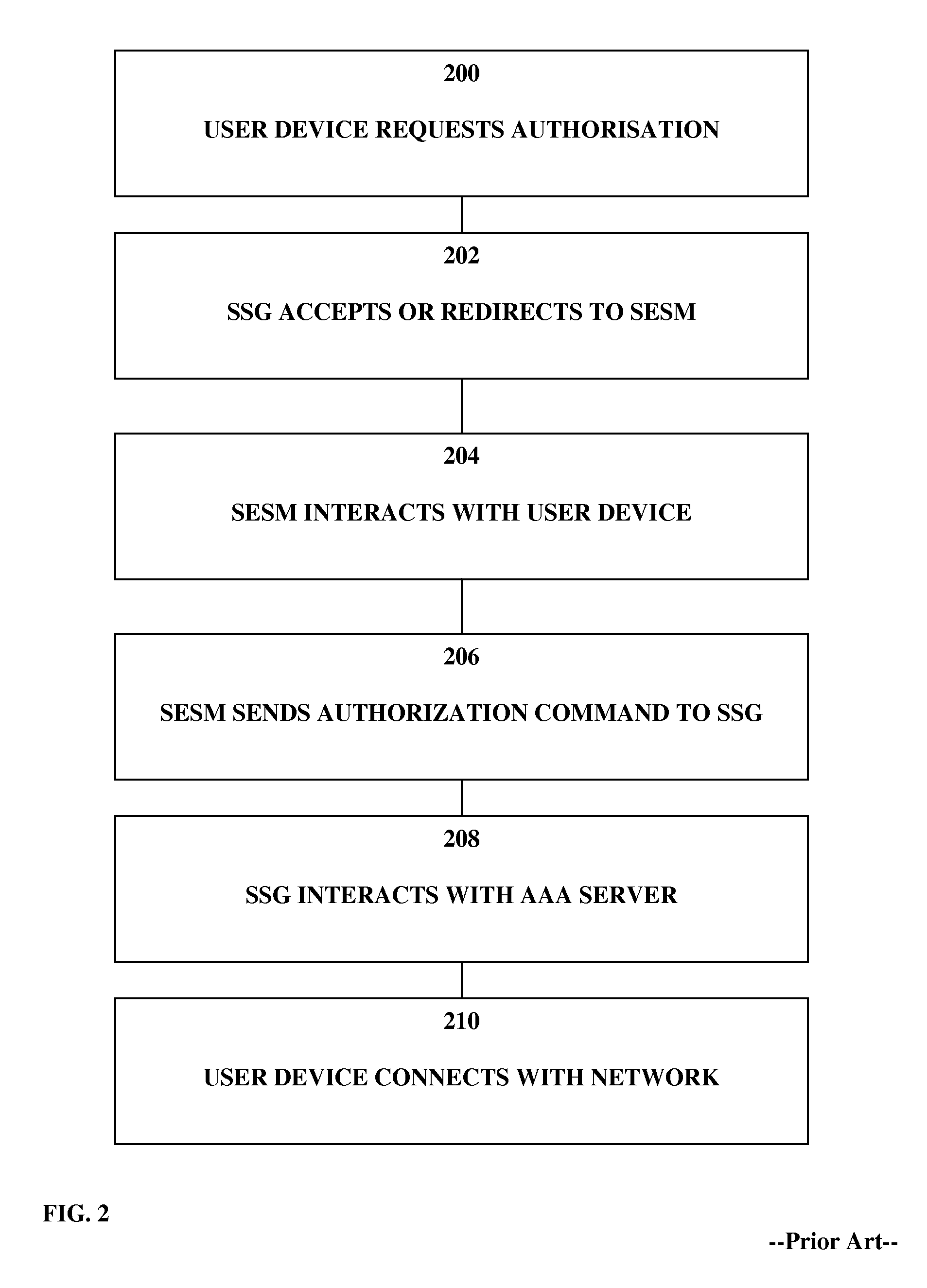
[0025]2.0 Structural and Functional Overview

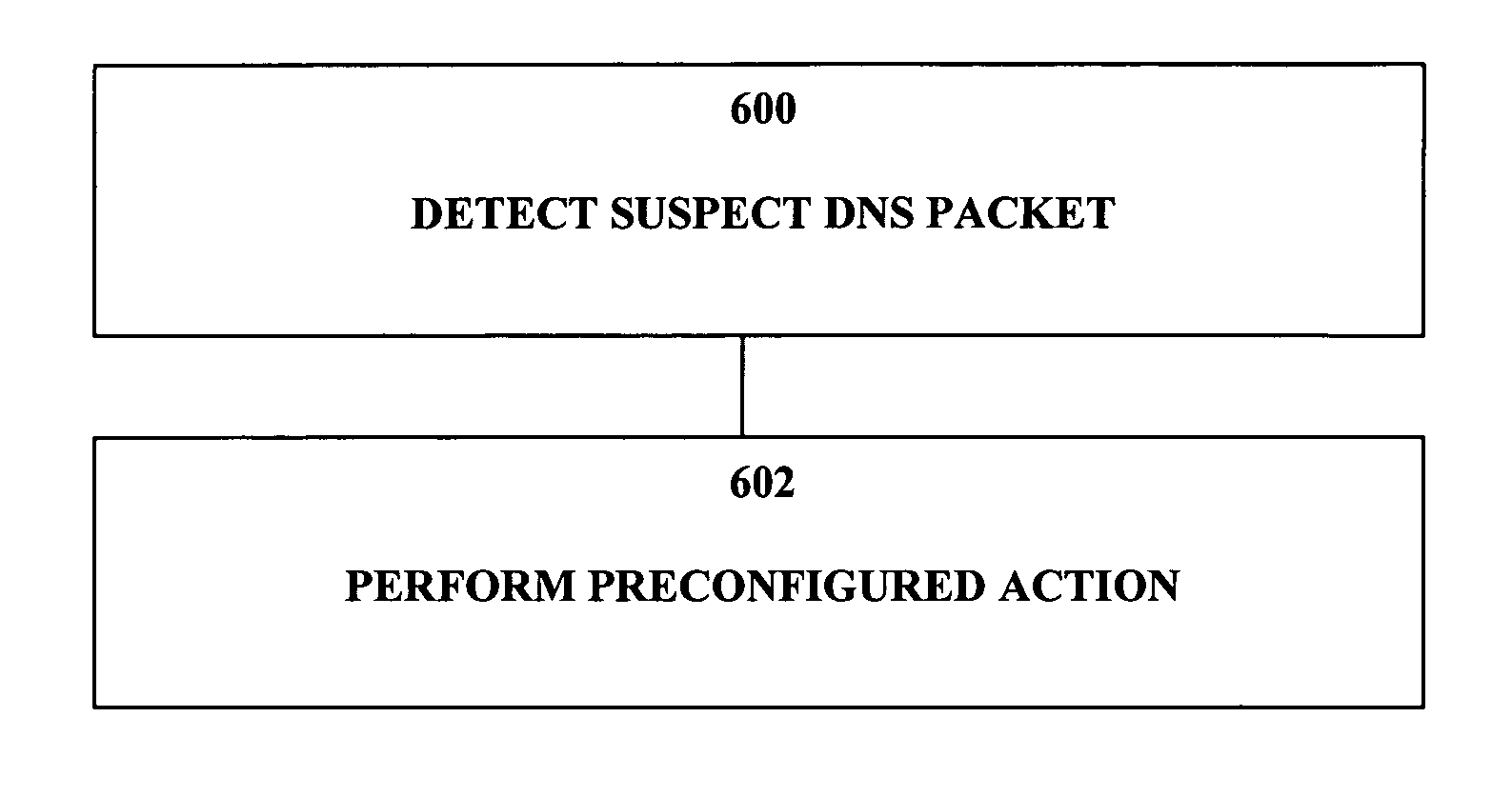
[0026]3.0 Method of Limiting DNS Transaction Bandwidth

[0027]4.0 Implementation Mechanisms—Hardware Overview

[0028]5.0 Extensions and Alternatives

[0029]1.0 General Overview

[0030]The needs identified in the foregoing Background, and other needs and objects that will become apparent for the following description, are ...


PUM


Abstract

A method of limiting domain name server (DNS) transaction bandwidth comprises intercepting one or more DNS packets, examining said one or more packets for the presence of a suspect transaction criterion and, if said suspect transaction criterion is present, implementing a transaction bandwidth limitation action.

Description

FIELD OF THE INVENTION[0001]The present invention generally relates to domain name server transactions. The invention relates more specifically to a method and apparatus for limiting domain name server transaction bandwidth.BACKGROUND OF THE INVENTION[0002]The approaches described in this section could be pursued, but are not necessarily approaches that have been previously conceived or pursued. Therefore, unless otherwise indicated herein, the approaches described in this section are not prior art to the claims in this application and are not admitted to be prior art by inclusion in this section.[0003]In a network such as a public wireless local area network (PWLAN) or “hotspot”, user devices such as a laptop, cell phone or personal digital assistant (PDA) are typically authorized upon connection to the network and an appropriate billing method applied. For example referring to FIG. 1 which is an illustrative network diagram of a PWLAN designated generally 100 a user device 102 con...

Claims


Application Information

Patent Timeline
IPC IPC(8): G06F15/173
CPCH04L63/0236H04L63/1441H04L63/1416H04L63/0245
Inventor BURSHAN, CHEN YEHEZKELCOTTON, IAN MICHAELMANNING, MICHAELWILKINS, GREGORY JOHN
Owner CISCO TECH INC
Why Eureka
Try Eureka