Beam shoe

a beam shoe and bottom technology, applied in the field of beam shoes, can solve the problems of unsatisfactory for the desired goal, and possibly even inadmissible sagging and achieve the effect of a distinct increase of the section modulus of the beam shoe bottom

Inactive Publication Date: 2011-07-05
SIMPSON STRONG TIE
View PDF105 Cites 16 Cited by
  • Summary
  • Abstract
  • Description
  • Claims
  • Application Information

AI Technical Summary

Benefits of technology

[0010]The object of the present invention is to improve the beam shoe of the class described hereinabove especially to the effect that it can be formed from a blank created with low losses, preferably substantially without losses, while achieving a distinct increase of the section modulus of its bottom by means of a reinforcing flange provided in the region thereof, wherein, by virtue of the achievable bottom reinforcement, it can be used with a sheet thickness that if necessary is smaller than that of conventional beam shoes, such as 1.5 mm and less, and wherein, despite the achieved reinforcement, flush contact between the beam to be attached and the load-bearing construction / the second beam is possible without having to recess it (or the load / bearing construction / the second beam) in the region of the reinforcing flange.
[0011]This object is achieved according to the invention by the fact that the (bottom) reinforcing flange is formed by a strip-like sheet-metal portion running in the plane of the two fastening flanges, the sheet-metal portion extending at least over the entire width of the bottom between the lower end portions of the two retaining legs adjacent the bottom. Thereby the bottom provided with the reinforcing flange forms, together with the lower end portions of the two retaining flanges, a three-dimensional structure of high rigidity, and it can absorb the bending forces and torques developed at the bottom-corner edges largely without deformation.
[0013]In this beam shoe, the channel-shaped retaining member comprising the two retaining legs and the bottom is therefore surrounded virtually all around, along its border facing the load-bearing construction / the second beam, by an integral, channel-shaped sheet-metal portion extending at right angles to the bottom and to the two fastening flanges, since the bottom reinforcing flange continues upward beyond the bottom and at its two ends merges into the respective fastening flange. Preferably, however, this surrounding portion is narrower in the region of the bottom and in a contiguous lower portion thereabove than in the region of the fastening flanges. This leads not only to a very considerable increase of the section modulus in the bottom region, wherein the bending torques developed under corresponding transverse-force load or the forces resulting therefrom can be diverted by that lower portion of the channel-shaped retaining member which is provided with the reinforcing flange into the fastening flange and then be absorbed thereby, but also to a possible decrease of the sheet-metal thickness for the same load and, last but not least, to the possibility of cutting the sheet-metal blank without losses.
[0015]In another configuration, in which the fastening flanges may also be bent over inwardly if necessary from the retaining flanges, and in which the sheet-metal portion forming the reinforcing flange is bent over inwardly at right angles in a manner known in itself, this sheet-metal portion bears firmly with its two end faces against the respective inside of the lower end portion of one retaining flange, and preferably does so under (compressive) stress, so that—differently from in the prior art, in which the end faces of the reinforcing flange are spaced apart from the insides of the retaining flanges—a highly bending-resistant structure is also obtained in the bottom region of the beam shoe when it is in assembled condition, even if the reinforcing flange is not joined to the retaining flanges (especially by welding), since it is firmly clamped between the beam to be attached and the load-bearing construction / the second beam, and therefore cannot slip out due to possible buckling, and therefore can transmit the bending torques or forces imposed on it to the retaining legs.

Problems solved by technology

In beam shoes of the class in question, without bottom reinforcing flange, undesired or possibly even inadmissible sagging of the beam-shoe bottom occurs during relatively large load on the beam to be attached as a result of transverse forces acting vertically on the bottom of the beam shoe.
In order to counteract or at least largely prevent this “cable effect”, bead-like stiffening ribs have been pressed into the bottom, but they have not led to an adequate increase of the section modulus compared with an unshaped bottom.
Nevertheless, even these configurations are not yet satisfactory for the desired goal of a substantially bending-proof bottom, since these tongues are narrower than the bottom and therefore are joined only to that bottom, but not to the retaining legs, and so the section modulus can be increased to only a limited extent in the lower portion of the channel-shaped retaining member.
A further disadvantage of known beam shoes of the class in question is that their blanks cannot be cut with low losses or even without losses, since the sheet-metal portion forming the reinforcing flange in the finished beam shoe protrudes in the manner of a tongue beyond the same bending line of the blank in the region of the middle blank portion forming the bottom after shaping.
However, this feature would lead to weakening of the bottom, even though its bending resistance is supposed to be increased with this feature.

Method used


Image

  • Beam shoe
  • Beam shoe
  • Beam shoe

Examples


Embodiment Construction

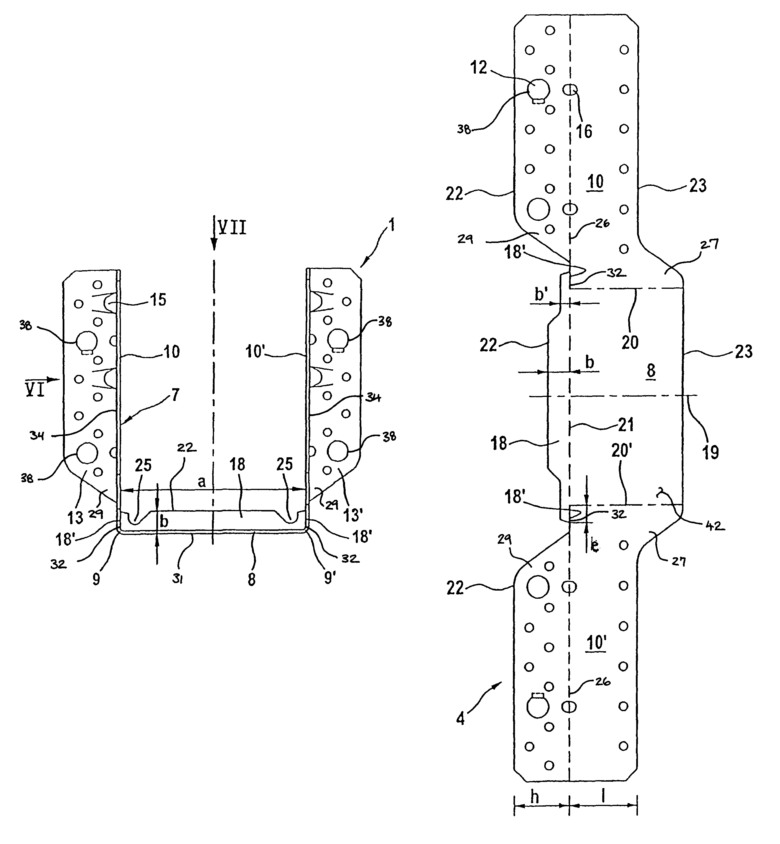
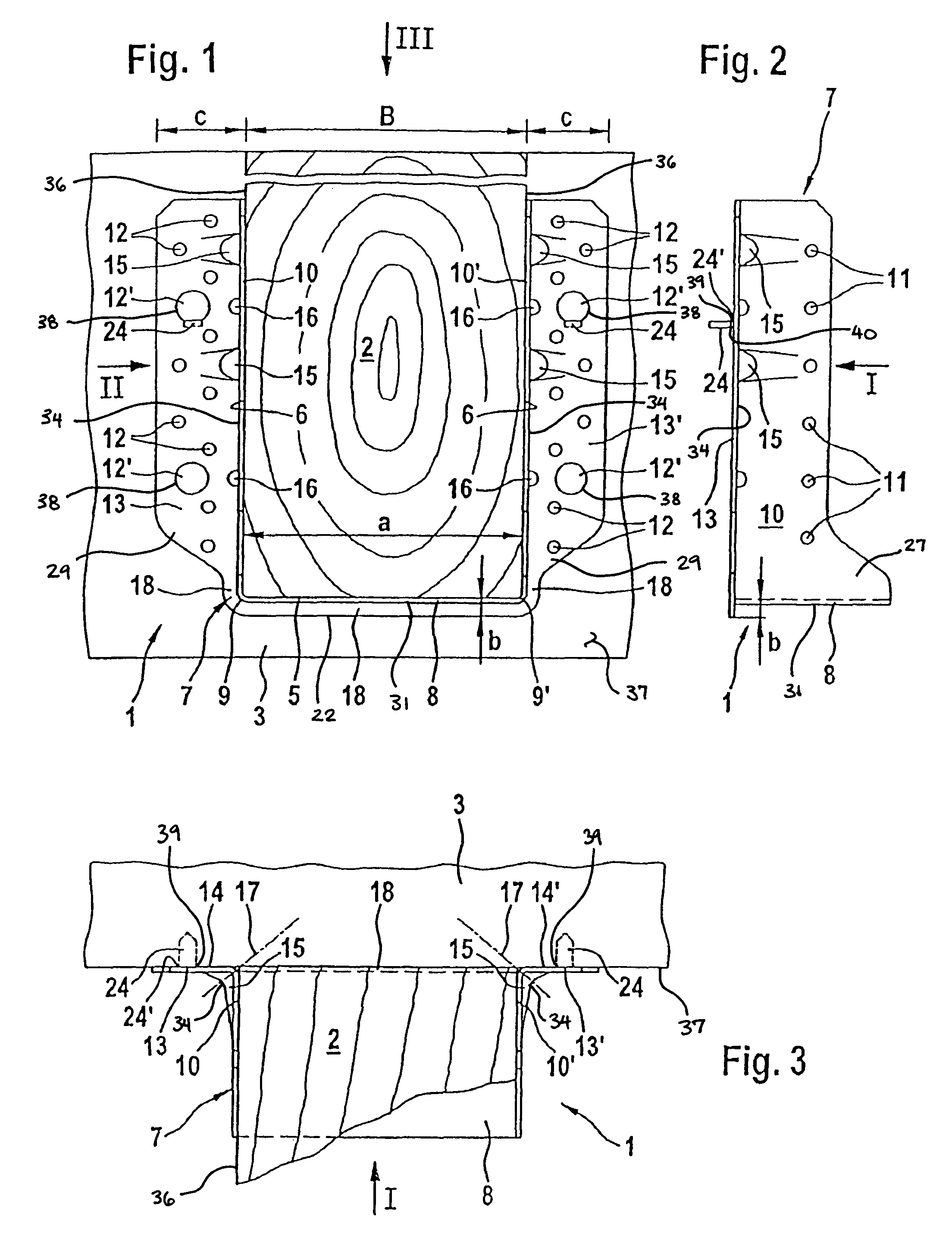
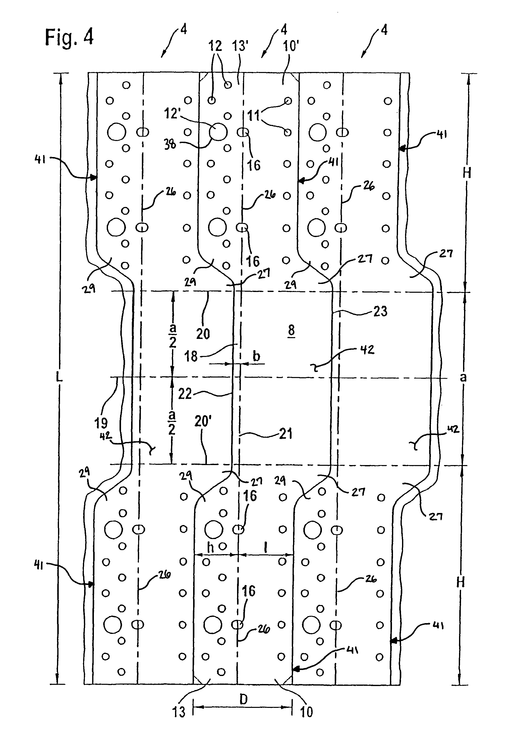
[0080]FIGS. 1 to 3 show a beam shoe denoted as a through hole by 1 for end-on attachment of a first beam 2 to a second beam 3 running in the same plane at right angles to the first beam 2. Beam shoe 1 comprises an originally flat, one-piece, strip-like sheet-metal blank 4 (see FIG. 4), which in the assembled condition (see FIGS. 1, 3) surrounds an end portion of beam 2 to be attached at its underside 5 and its side faces 6, 6 and is shaped to an upwardly open, channel-shaped retaining member 7 having a web-like, rectangular bottom 8 for bracing beam 2 to be attached on beam shoe 1 and having two web-like, parallel retaining legs 10, 10′, angled upwardly from bottom 8 along two mutually facing borders 9, 9′ of border 8, for joining beam shoe 1 to beam 2 to be attached. Therein the inside spacing “a” between the two retaining legs 10, 10′ is as large as the width “B” of first beam 2 to be attached, and the two retaining legs 10, 10′ are each provided with circular through holes 11 dis...


PUM

PropertyMeasurementUnit
thicknessaaaaaaaaaa
thicknessaaaaaaaaaa
widthaaaaaaaaaa

Abstract

A beam shoe for attaching a (first) beam end-on to a load-bearing construction, especially to a second beam disposed in the same plane as the beam to be attached and running at right angles thereto, the beam shoe comprising an originally flat, one-piece, strip-like sheet-metal portion or blank, which is shaped to an upwardly open channel-shaped retaining member having a web-like rectangular bottom for bracing the beam to be attached on the beam shoe as well as two web-like, parallel retaining legs, the retaining member embracing, in assembled condition, an end portion of the beam to be attached at the underside and side faces thereof, the legs, which are bent over upwardly from the bottom at right angles and disposed along two opposite borders of the bottom, being provided with through holes for rod-like fasteners such as nails in particular in order to join the beam shoe to the beam to be attached, the inside spacing of the legs therefore being (at least) as large as (and if necessary somewhat larger than) the width of the beam to be attached, wherein a fastening flange provided with through holes for rod-like fasteners such as nails and / or screws is bent over at right angles along that longitudinal border of each retaining leg which faces the load-bearing construction (or if necessary the second beam), the fastening flange being designed to be placed with its outside face remote from the channel-shaped retaining member of the beam shoe on the load-bearing construction / the second beam and to be fastened thereto with rod-like fasteners such as nails and / or screws, and wherein the web-like bottom is reinforced by a (bottom) reinforcing flange or the like in order to increase its section modulus against sagging under relatively large load.

Description

BACKGROUND OF THE INVENTION[0001]The present invention relates to a beam shoe for attaching a (first) beam end-on to a load-bearing construction, especially to a second beam disposed in the same plane as the beam to be attached and running at right angles thereto, the beam shoe comprising an originally flat, one-piece, strip-like sheet-metal portion or blank, which is shaped to an upwardly open channel-shaped retaining member having a web-like rectangular bottom for bracing the beam to be attached on the beam shoe as well as two web-like, parallel retaining legs, the retaining member embracing, in assembled condition, an end portion of the beam to be attached at the underside and side faces thereof, the legs, which are bent over upwardly from the bottom at right angles and disposed along two opposite borders of the bottom, being provided with through holes for rod-like fasteners such as nails in particular in order to join the beam shoe to the beam to be attached, the inside spacing...

Claims


Application Information

Patent Timeline
Patent Type & Authority Patents(United States)
IPC IPC(8): E04C5/01E04C5/02E04B1/26
CPCE04B1/2612Y10T29/49632
Inventor BAK, JEPPE MOLB.AE BUTTED.KBENTSEN, HENRICKHARRISON, IANIPSEN, JORNMATHIS, CHARLES-HENRI
Owner SIMPSON STRONG TIE
Why Eureka
Try Eureka