Actively regulated modulation index for contactless IC devices

a contactless ic device and modulation index technology, applied in the field of regulating the modulation index of ask modulated carrier waves, can solve the problems of increasing complexity of demodulators

Active Publication Date: 2011-07-05
INFINEON TECH AG
View PDF27 Cites 18 Cited by
  • Summary
  • Abstract
  • Description
  • Claims
  • Application Information

AI Technical Summary

Problems solved by technology

The wide range of acceptable modulation indices has caused compatibility issues with conventional demodulator circuits and thereby increased demodulator requirements resulting in increasingly complex demodulators.

Method used


Image

  • Actively regulated modulation index for contactless IC devices
  • Actively regulated modulation index for contactless IC devices
  • Actively regulated modulation index for contactless IC devices

Examples


Embodiment Construction

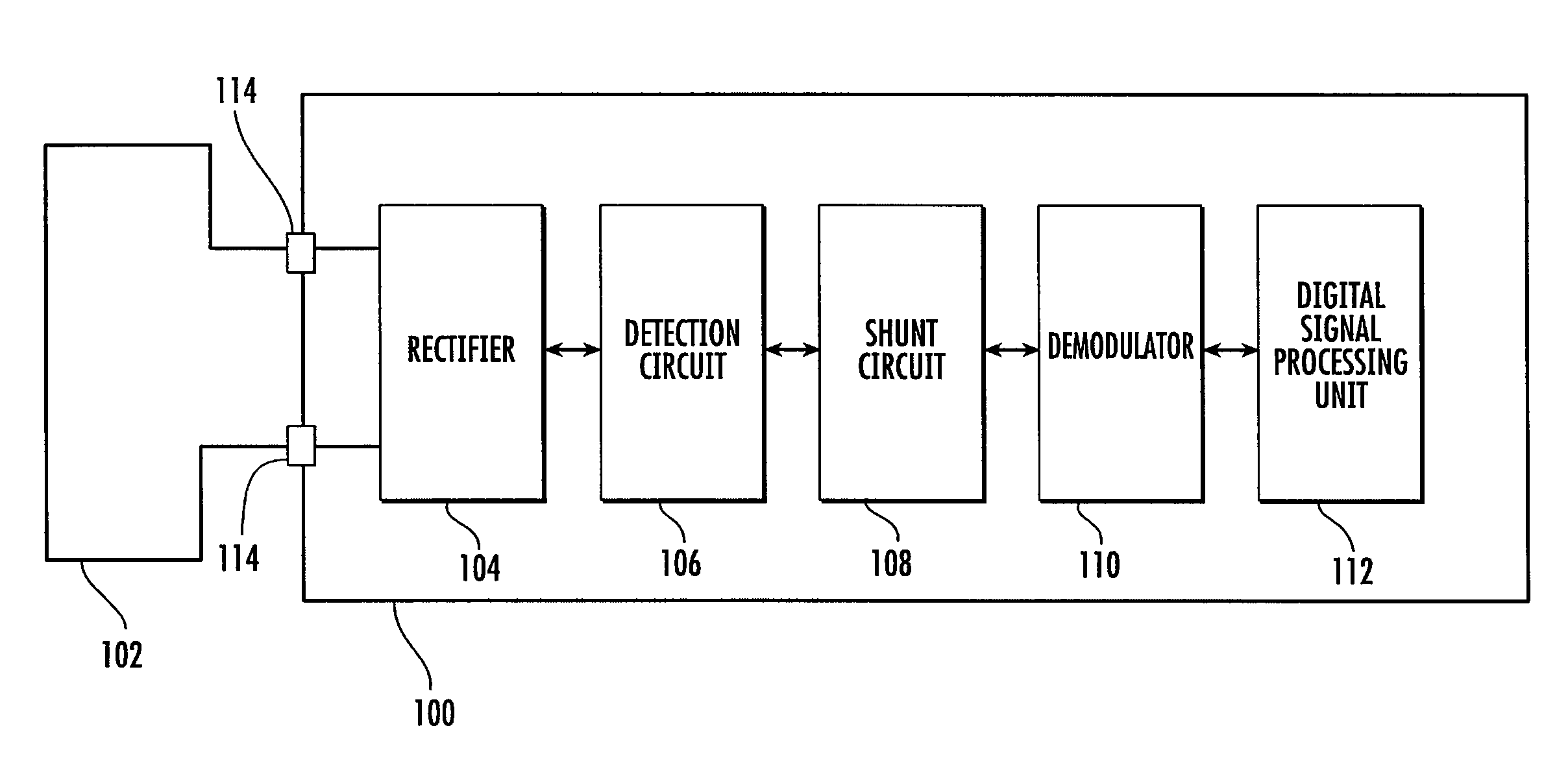
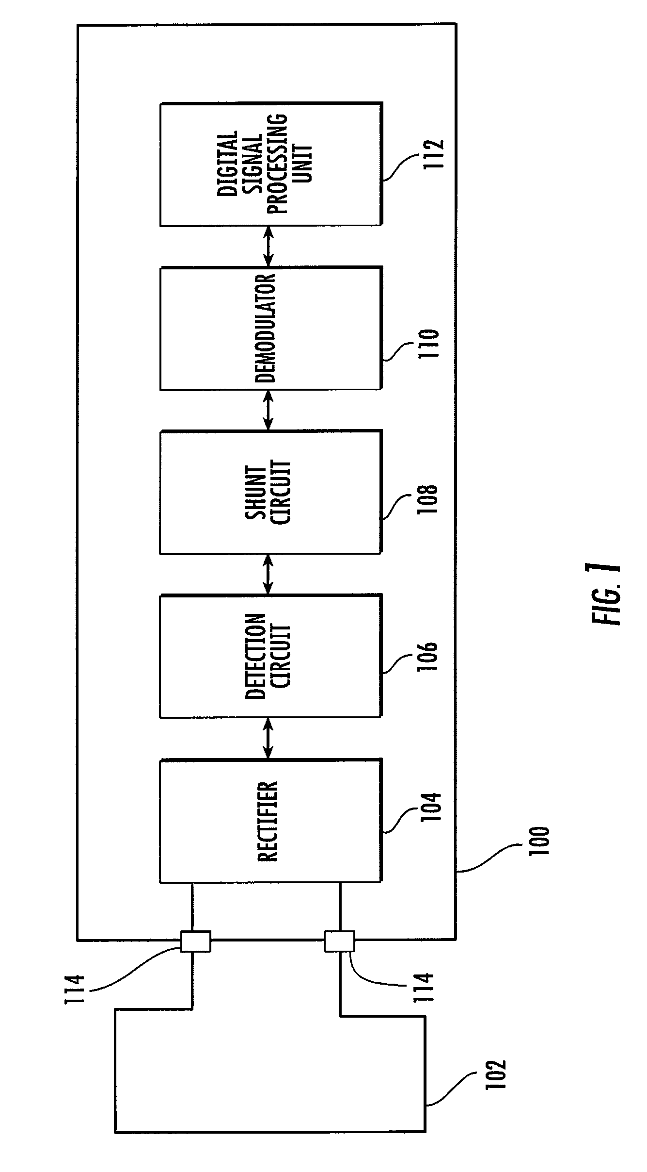
[0010]A contactless IC device according to an embodiment of the present invention will be described with reference to FIG. 1. FIG. 1 is a block diagram showing a construction of a contactless IC device 100 configured to actively regulate a modulation index at coil contacts 114 between two stable values (e.g., V1 and V2), independent of the applied modulation index of an ASK modulation.

[0011]Contactless IC device 100 includes a coil antenna 102 for receiving electromagnetic wave energy that is transmitted from an external device. Coil antenna 102 serves as an antenna for transmitting / receiving carrier waves, which have been ASK modulated with data, to and from the contactless IC device 100. Carrier waves received by coil antenna 102 are rectified by rectifier 104 to generate a power supply voltage.

[0012]Rectifier 104 is connected to the coil antenna 102 and serves to convert the carrier wave into a DC power supply voltage. Rectifier 104 is a full-wave rectification circuit and can be...


PUM


Abstract

A contactless IC device including a detection circuit configured to detect a carrier wave that has been amplitude shift-keying (ASK) modulated with digital data and a shunt circuit configured to regulate the carrier wave to a predetermined voltage level.

Description

FIELD OF THE INVENTION[0001]The present invention relates to regulating the modulation index of ASK modulated carrier waves at the input of a contactless IC device.BACKGROUND OF THE INVENTION[0002]Contactless IC (integrated circuit) devices, also known as chip cards or smart cards, operate on the basis of communication by an electromagnetic field with a read and / or write interrogating device, generically referred to as a reader.[0003]In contactless IC device applications, the reader typically transmits an electromagnetic carrier wave having a carrier frequency of 13.56 MHz. This transmitted carrier wave serves on the one hand to power the contactless device, which thus derives by induction the energy required for its operation, and on the other hand to set up a communication between the device and the reader according to an established communication protocol. Thus, when the contactless device penetrates into the transmission field of the reader, it communicates with the latter by a ...

Claims


Application Information

Patent Timeline
Patent Type & Authority Patents(United States)
IPC IPC(8): G06K19/06G06K7/08G06K19/00
CPCH04L27/08H04L27/04
Inventor LEUTGEB, THOMASKARGL, WALTERSBUELL, RICHARDIBRAHIMAGIC, EDINMISSONI, ALBERT
Owner INFINEON TECH AG
Why Eureka
Try Eureka