
Fuel injector

a fuel injector and injector technology, applied in the direction of fuel injectors, machines/engines, mechanical equipment, etc., can solve the problems of troublesome adaptation of the ncv described in wo 2004, 005702, to high-pressure applications

Active Publication Date: 2011-07-05
DELPHI TECH IP LTD
View PDF16 Cites 11 Cited by
  • Summary
  • Abstract
  • Description
  • Claims
  • Application Information

AI Technical Summary

Benefits of technology

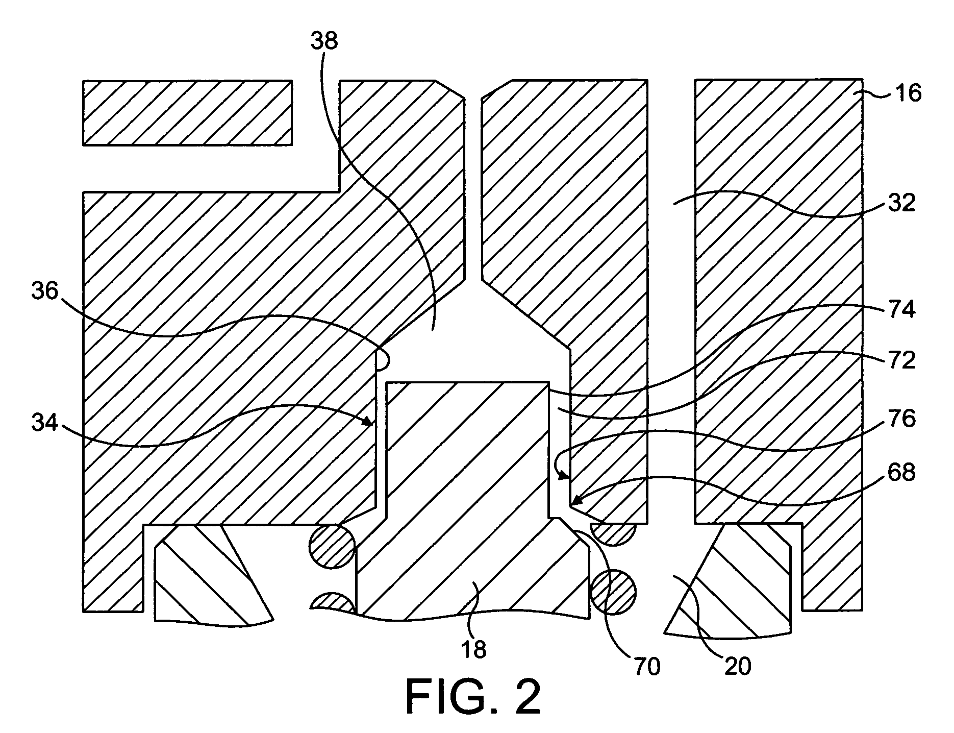
"The invention is a fuel injector for delivering fuel to an internal combustion engine. It includes a nozzle with a needle that can be moved to control fuel delivery. The nozzle needle has a restricted passage that controls the rate at which the control chamber depressurizes, which in turn controls the movement of the needle. The restricted passage allows fuel to flow into the control chamber during pressurization, reducing parasitic losses. The fuel injector also includes a second needle seat that prevents fuel flow when the needle is lifted from the first needle seat. The restricted passage is defined by the outer surface of the needle and the surface of the bore in which it moves. The patent text describes various ways to control the restricted passage, including using a cavity wall that contracts inwardly when fuel pressure is reduced. The patent also mentions an additional restricted passage that allows fuel to flow out of the control chamber during pressurization. The technical effects of the invention include improved control of fuel delivery and reduced parasitic losses."

Problems solved by technology

Adapting the NCV described in WO 2004 / 005702 for use in high-pressure applications can be problematic because of the configuration of the NCV which is necessary to provide the restricted flow path.

Method used


Image

  • Fuel injector
  • Fuel injector
  • Fuel injector

Examples


Embodiment Construction

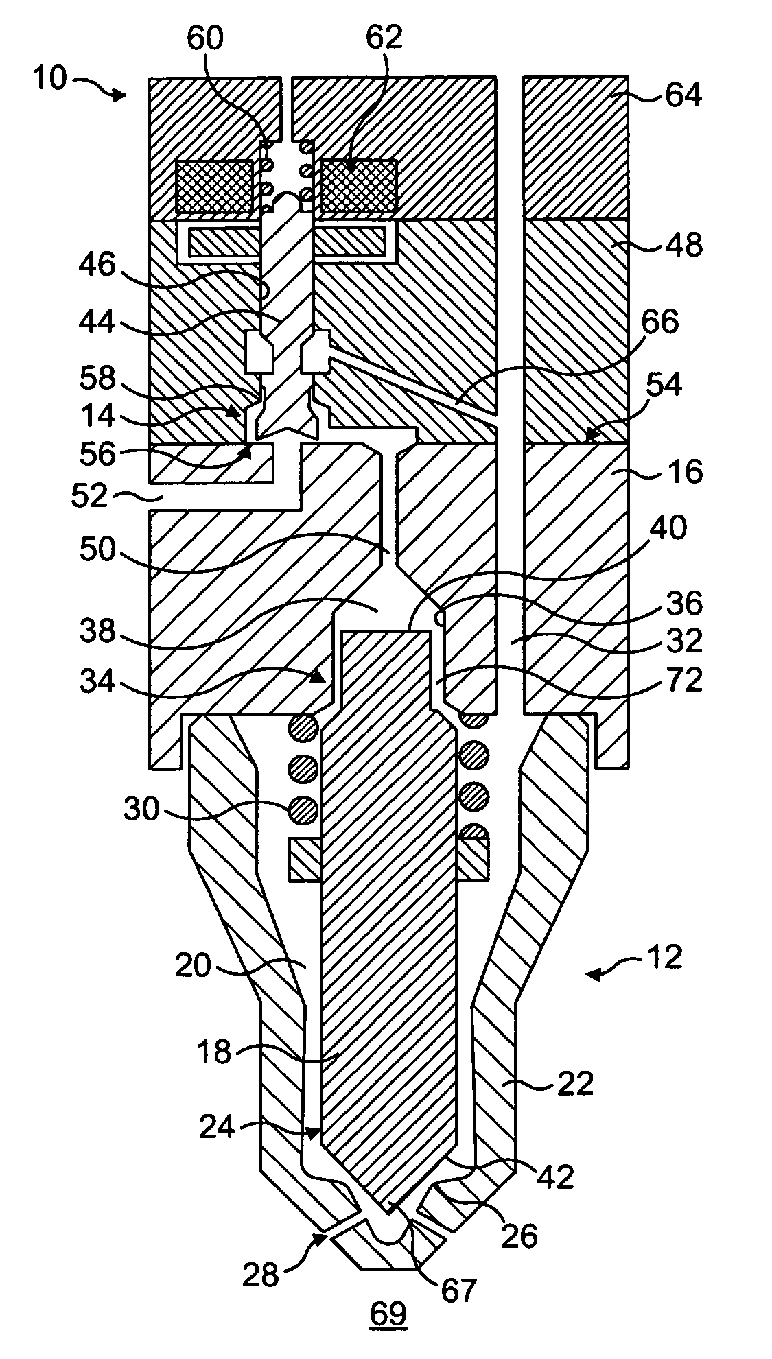
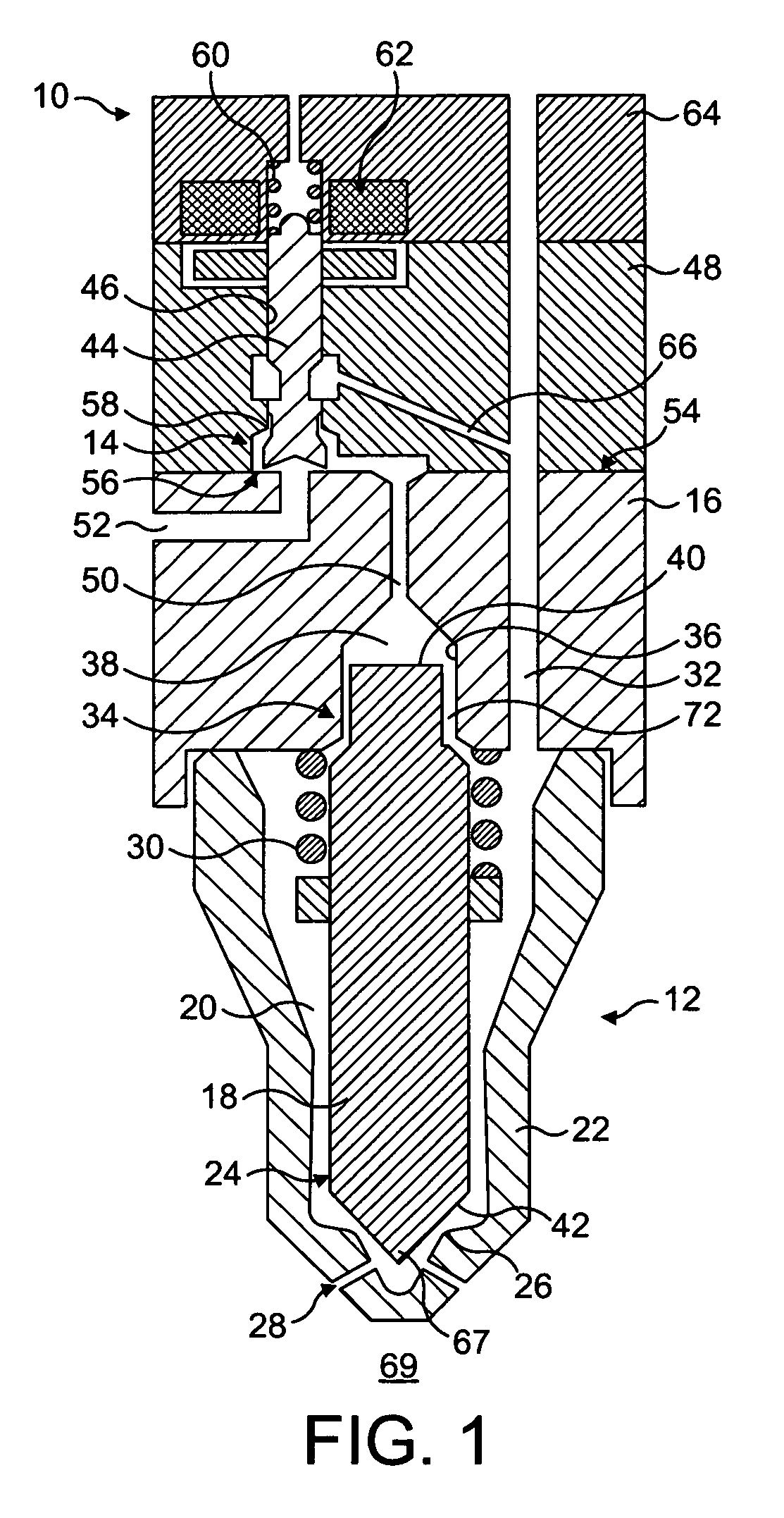
[0025]FIG. 1 is a schematic cross-sectional view of a fuel injector 10 for use in delivering fuel to an engine cylinder or other combustion space of an internal combustion engine. The fuel injector 10 comprises an injector nozzle 12 and a three-way nozzle control valve (NCV) 14. An injector body 16 connects the injector nozzle 12 and the NCV 14.

[0026]The nozzle 12 comprises a nozzle needle 18 that is slidable within a nozzle chamber 20 defined within a nozzle body 22. A lower end 24 of the nozzle needle 18 terminates in a nozzle tip 67 and is engageable with a first needle seat 26 defined by the nozzle body 22 so as to control fuel delivery through a set of outlet openings 28 provided in the nozzle body 22 into a combustion space 69. The nozzle 12 includes a spring 30 for biasing the nozzle needle 18 towards the first needle seat 26. Fuel under high pressure is delivered from a fuel supply to the nozzle chamber 20, in use, through a supply passage 32 defined, in part, within the inj...


PUM


Abstract

A fuel injector comprising a nozzle having a nozzle needle which is moveable with respect to a first needle seat to control fuel delivery through a nozzle outlet. The injector includes a nozzle control valve for controlling fuel flow into a control chamber through a first passage to pressurise the control chamber, and for controlling fuel flow out of said control chamber through said first passage to depressurise the control chamber. Movement of the nozzle needle is controlled by fuel pressure within the control chamber, such that pressurising the control chamber causes the nozzle needle to be urged against the first needle seat to close the nozzle outlet, and depressurising the control chamber causes the nozzle needle to lift from the first needle seat to open the nozzle outlet. The nozzle needle defines, at least in part, a restricted passage through which fuel can flow into the control chamber as the control chamber depressurises. The fuel flow into the control chamber through the restricted passage serves to reduce the rate at which the control chamber depressurises, thereby reducing the rate at which the nozzle needle lifts from the first needle seat to open the nozzle outlet.

Description

TECHNICAL FIELD[0001]The invention relates to a fuel injector for use in the delivery of fuel to a combustion space of an internal combustion engine, and particularly to a fuel injector suitable for delivering small quantities of fuel across a wide range of fuel pressures.BACKGROUND TO THE INVENTION[0002]To optimise diesel engine combustion, it is necessary to have precise control over the quantities of fuel delivered by the fuel injectors. It is desirable to be able to inject small quantities of fuel across a wide range of fuel pressures. For heavy-duty applications in particular, the fuel injectors must be capable of delivering fuel in small quantities at very high fuel pressures.[0003]Typically, a fuel injector includes an injection nozzle having a nozzle needle which is movable towards and away from a nozzle needle seating so as to control fuel injection into the engine. The nozzle needle is controlled by means of a nozzle control valve (NCV), which controls fuel pressure in a c...

Claims


Application Information

Patent Timeline
Patent Type & Authority Patents(United States)
IPC IPC(8): F02M41/16
CPCF02M45/12F02M47/027F02M61/042F02M63/0045F02M63/0015F02M63/0043F02M2200/28F02M2200/304F02M2547/008
Inventor MALE, ANDYWRAY, JONATHAN NHARCOMBE, ANTHONY THOMASPIMENTA, RICARDOLAMBERT, MALCOLM DAVID DICKLIMMER, ANDREW J
Owner DELPHI TECH IP LTD
Learn More