Chromatography columns and their operation

a technology of chromatography column and movable end plate, which is applied in the field of chromatography column, can solve the problems of serious difficulties in keeping the end unit exactly level, the control of the sliding movement of the movable end plate, and the difficulty in keeping the end unit level

Inactive Publication Date: 2011-07-05
PALL CORP
View PDF37 Cites 5 Cited by
  • Summary
  • Abstract
  • Description
  • Claims
  • Application Information

AI Technical Summary

Problems solved by technology

Controlling the sliding movement of a movable end plate is technically problematic, especially with large columns.
Whichever is used, there can be serious difficulties in keeping the end unit exactly level, i.e., in achieving exactly the same movement in all of the peripheral drive rods.
However, these are expensive and complicated.
The mentioned fixed pillars and drive rods already cause obstruction around the column, to the extent that it can be difficult to access the column interior for maintenance operations, e.g., removal / insertion of replacement permeable layers.
It is highly undesirable to add to the obstruction and complication with further drive control mechanisms.

Method used


Image

  • Chromatography columns and their operation
  • Chromatography columns and their operation
  • Chromatography columns and their operation

Examples


Embodiment Construction

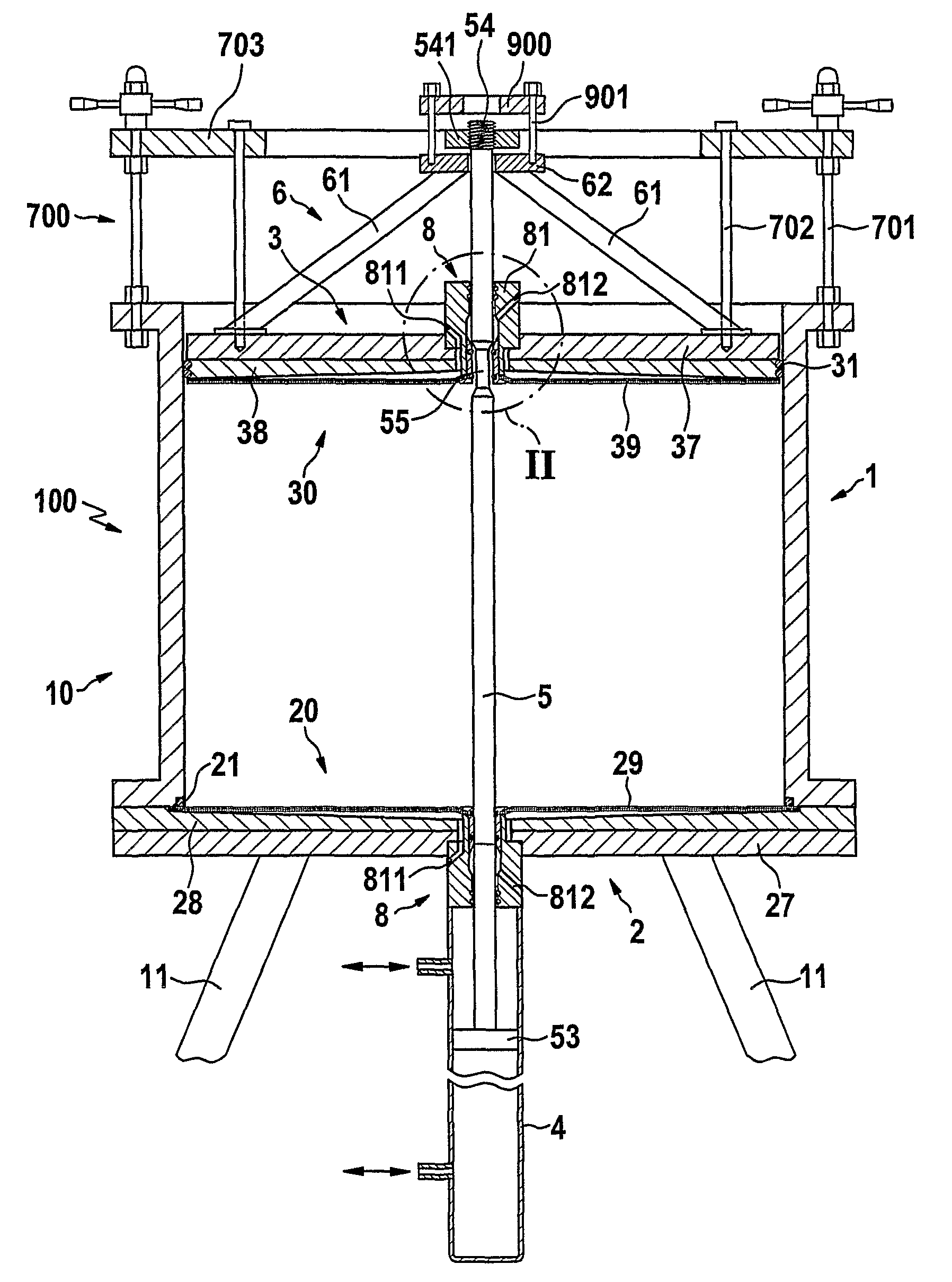
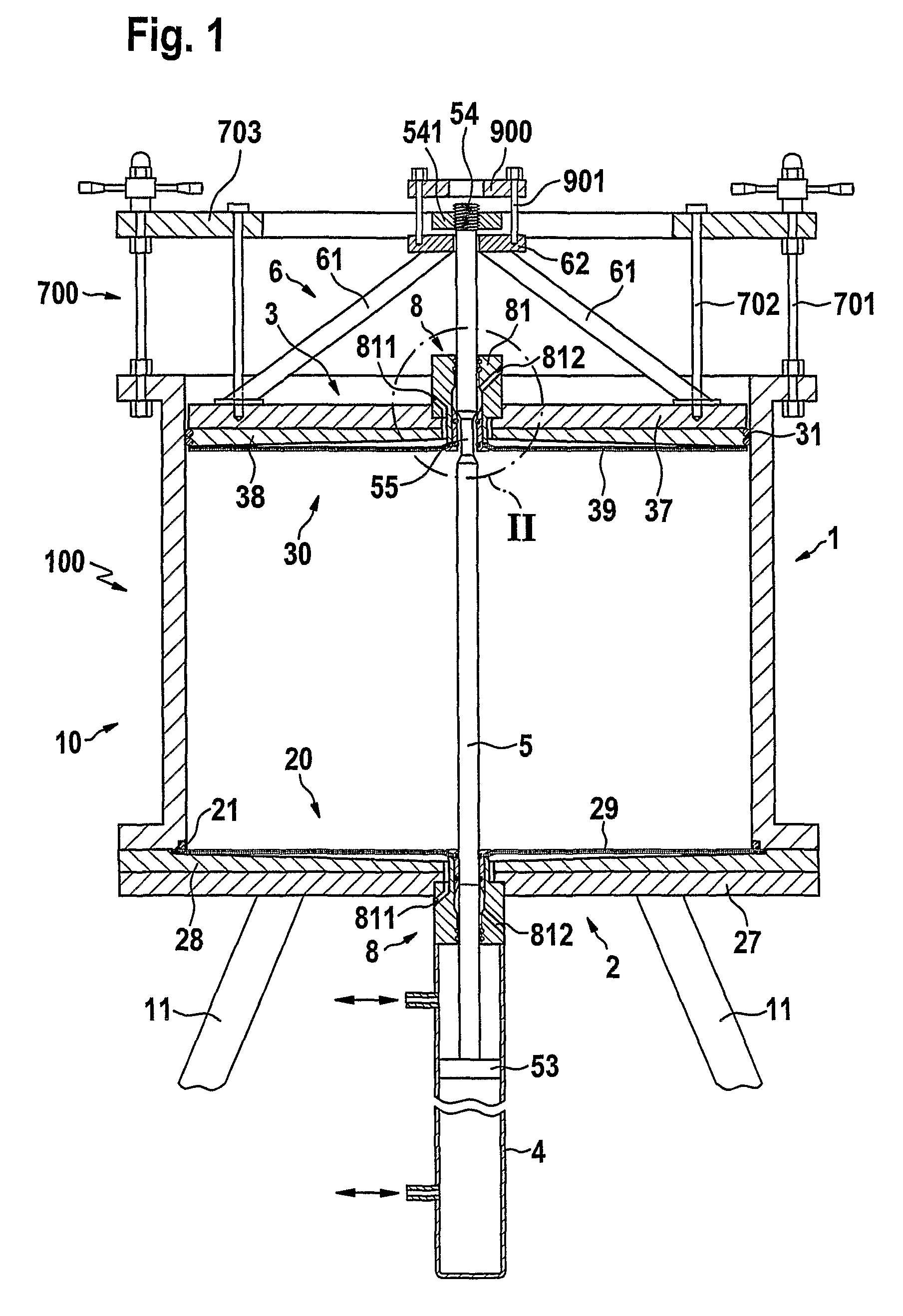
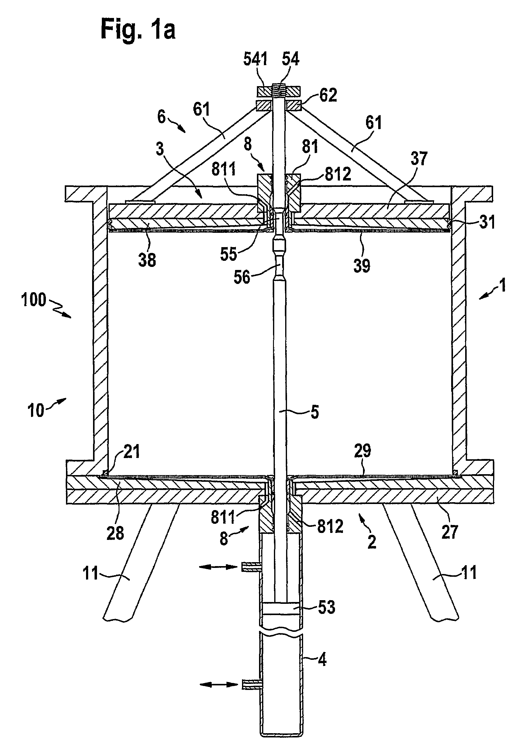
[0026]In an embodiment of a chromatography column comprising a housing and having an internal bed space and opposing end units, an axial drive element, which extends internally in the column bed space, is connected to an axially slidable column end unit, and connects to a drive, on or beyond the opposite end unit. By providing axial drive connection structure internally of the bed, bulky support and drive structures outside the column housing can be reduced or eliminated.

[0027]Advantageously, it has been found that a drive element extending axially through the bed space, in contact with the bed, need not seriously affect chromatography performance.

[0028]Naturally, the internal drive element is preferably centrosymmetric. It is preferred to have a single axial drive element extending on the central axis of the column so as to act centrally on the slidable end unit. By providing a suitable connection structure for transferring axial tensile force from such a drive element to the slida...


PUM


Abstract

A chromatography column (100) is disclosed comprising a housing (10) comprising a tubular side wall (1); opposed, axially spaced end units (2,3) which together with the side wall define an enclosed bed space to contain a bed of particulate medium, at least one of the end units being slidable in axial direction; an axial drive element (5) connected to the slidable end unit, said drive element extending internally in the column bed space; a drive (4) positioned on or beyond the opposite end unit and connected to the drive element.

Description

REFERENCE TO RELATED APPLICATIONS[0001]This application is a 371 of PCT / US05 / 07413 filed Jul. 8, 2005.BACKGROUND OF THE INVENTION[0002]This invention relates to chromatography columns and methods of operating them. In particular, it relates to structures and methods useful in moving column end units, such as in packing and / or in unpacking a particulate medium which in use occupies a bed space of the column. The invention relates to any size column, and particularly relates to larger columns of the kind useful in industrial preparative chromatography, whose internal diameters might typically be from 200 mm upwards, perhaps up to 3000 mm.[0003]A conventional industrial-scale chromatography column consists of a column housing having a tubular side wall—almost always cylindrical—and opposed axially spaced end units (commonly referred to as plates, or end plates), which together with the side wall define an enclosed bed space to contain a bed of particulate medium in use. For most proces...

Claims


Application Information

Patent Timeline
Patent Type & Authority Patents(United States)
IPC IPC(8): B01D15/08B01D15/22
CPCB01D15/22G01N30/6021G01N30/6004
Inventor HOFMANN, MARTIN JOHN
Owner PALL CORP
Why Eureka
Try Eureka