Method for manufacturing battery pack

a battery pack and resin molding technology, applied in the field of batteries, can solve the problems of high manufacturing cost of resin molding dies used in pack cases, battery packs using pack cases are not suited to portable electronic equipment that are re-modeled, and fire or explosion of batteries, so as to reduce heat conduction from resin to heat sensitive elements, good heat conductivity, and good heat conductivity

Inactive Publication Date: 2011-07-05
PANASONIC CORP
View PDF43 Cites 24 Cited by
  • Summary
  • Abstract
  • Description
  • Claims
  • Application Information

AI Technical Summary

Benefits of technology

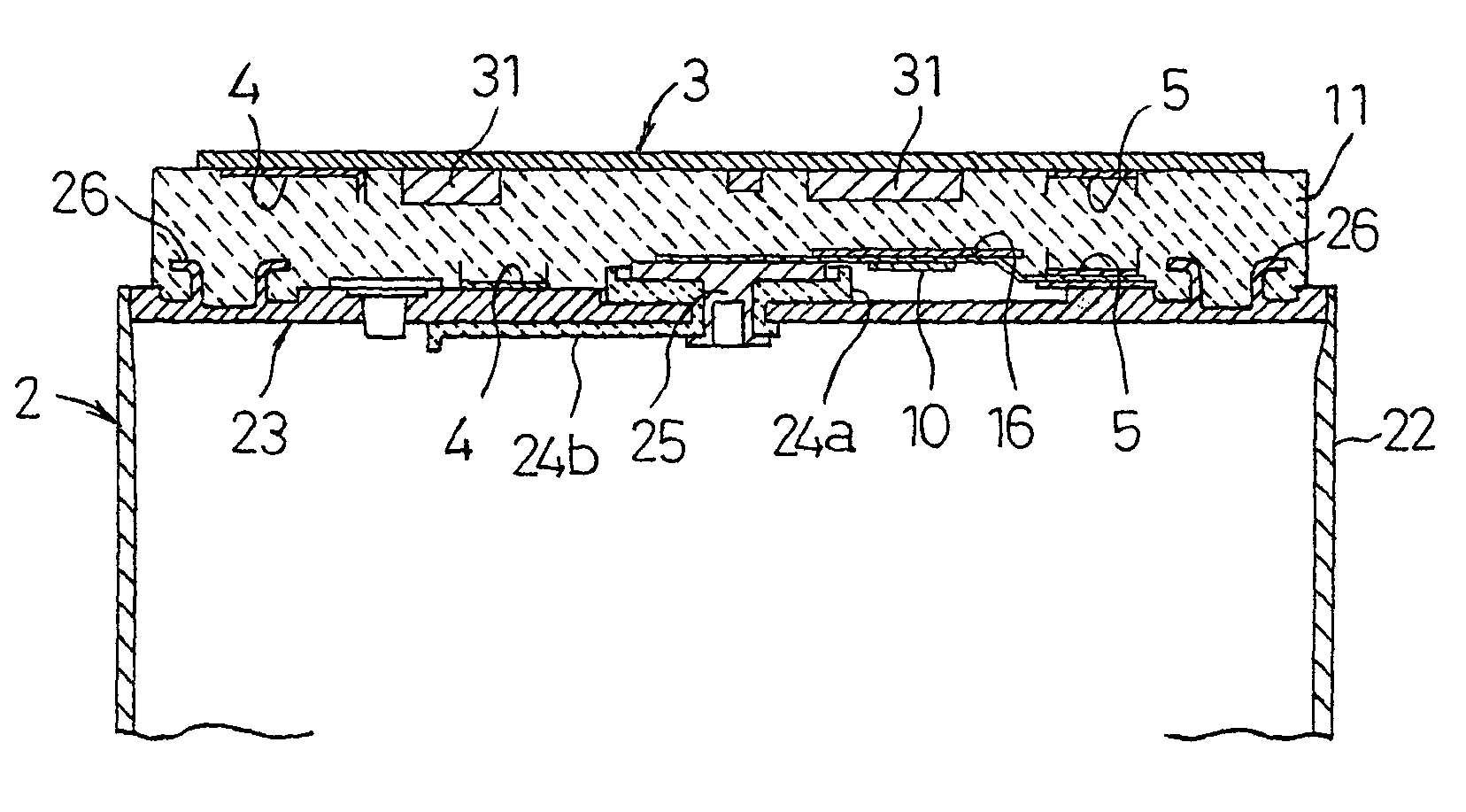
[0014]A battery pack according to a third aspect of the present invention comprises a substrate formed with an external terminal that is arranged on a sealing plate side of a rechargeable battery with a gap therebetween and united with the rechargeable battery by resin filled in that gap; and a heat sensitive element heat-coupled to the rechargeable battery that is arranged in a recess formed in the sealing plate and provided with a heat insulation member or other constituent elements covering the recess. Because the heat sensitive element is arranged in the recess that is covered by other constituent elements, the filled resin does not contact the heat sensitive element, and the battery pack is formed without the risk of destroying the heat sensitive element with the heat of molten resin during the resin filling. Further, heat of the rechargeable battery is well conducted to the heat sensitive element because it is arranged in the recess, and it operates swiftly in response to an abnormal temperature rise in the rechargeable battery.
[0016]and a heat sensitive element heat-coupled to the rechargeable battery that is arranged in the gap and formed with a heat insulation coating layer. The coating layer on the heat sensitive element has heat insulating properties, and a direct contact of the element with the high-temperature molten resin is avoided by arranging this side with the coating layer to contact the molten resin, whereby deterioration of its characteristics is prevented. With this structure, because the heat sensitive element is protected by the coating layer, there is no need of covering the element with a heat insulation member. By the elimination of the heat insulation means, the number of process steps and components in the production are reduced, whereby a cost reduction is achieved. The coating layer should preferably be made of a resin material having heat insulating properties. Further, the heat sensitive element should include a portion that is not provided with the coating layer so that it is contacted and heat-coupled to the rechargeable battery in that portion. Thus coating layer is not formed in the portion that is in contact with the rechargeable battery, whereby the heat sensitive element has both a heat shield during the resin molding and high sensing precision of the rechargeable battery temperature. In order to prevent an increase in the process steps and complication in the process of arranging the heat sensitive element on the rechargeable battery, a suitable resin material should be selected; it should be able to provide the heat shield effect during the short period of resin molding, and have thermal characteristics that do not cause a decrease in the sensing precision of the rechargeable battery temperature after the battery pack is complete. Thereby, the heat sensitive element has the heat shield and high sensing precision, and is provided with fewer process steps and at lower cost.
[0018]A method for manufacturing a battery pack according to a fifth aspect of the present invention comprises: arranging a substrate formed with an external terminal that is connected to a rechargeable battery, opposite the rechargeable battery with a gap therebetween for forming an object to be resin packed, which is placed inside a die; and filling the gap with resin for uniting the rechargeable battery and the substrate, wherein the die in which the object to be resin packed is placed and resin is filled in the gap is formed of a material having good heat conductivity at least in a portion corresponding to the position where a heat sensitive element arranged inside the gap is located. By forming the die from a material having good heat conductivity in the portion corresponding to the position of the heat sensitive element, heat of the filled resin conducts well to that portion made of the heat conductive material, whereby heat conduction from the resin to the heat sensitive element is reduced. The battery pack of the rechargeable battery united with the substrate by resin molding is thus produced without the risk of destroying the heat sensitive element by the heat of the filled resin.

Problems solved by technology

A temperature rise in the battery leads to a rapid increasing of inner gas pressure caused by reactions between positive electrode active materials and electrolyte, or from evaporation or decomposition of electrolyte, which results in fire or explosion of the battery.
However, battery packs using pack cases are not suited to portable electronic equipment that are re-modeled in short cycles, because the manufacturing cost of molding dies used in the resin molding of pack cases tends to be high, and the time required for designing new molding dies is relatively long.
Battery packs with resin-molded outer cases also have limitations in making portable electronic equipment smaller and thinner because of the limitations on the moldable thickness in the resin molding process.
A direct contact of molten hot melt resin with the temperature fuse will certainly induce fusion, whereby the circuit in the battery pack will be cut and not properly function.
In the case with a PTC element, hot resin of more than 200° C. will change the bridging structure of the conductive polymer that is a chief component of the PTC element, whereby the temperature-current characteristics and trip temperature will be affected and the reliability of the PTC element will be deteriorated.

Method used


Image

  • Method for manufacturing battery pack
  • Method for manufacturing battery pack
  • Method for manufacturing battery pack

Examples


Embodiment Construction

[0032]Preferred embodiments of the present invention will be hereinafter described with reference to the accompanying drawings for an understanding of the invention. It should be understood that the following embodiments of the invention are merely given as examples and should not limit the technical scope of the invention.

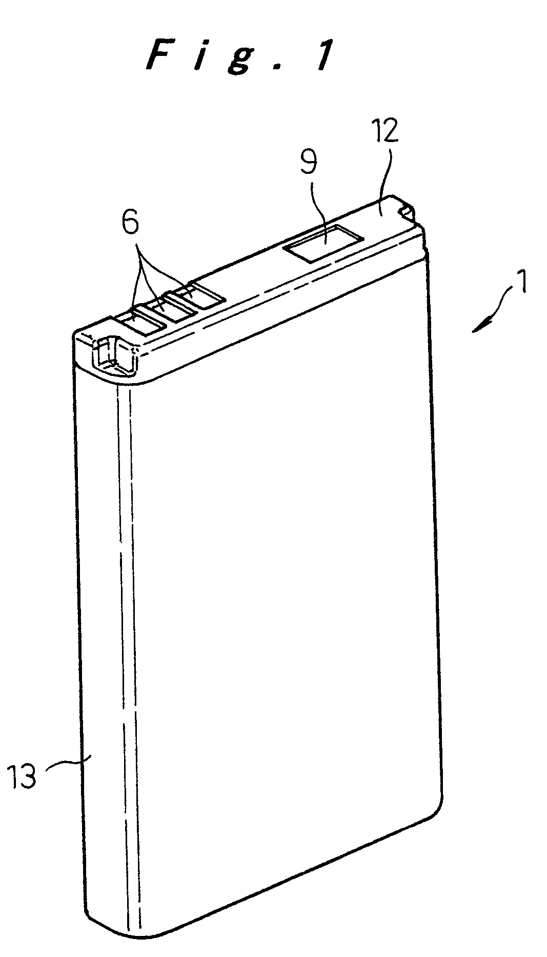
[0033]The present embodiment shows one example of a battery pack employing a flat prismatic lithium ion rechargeable battery applied to a mobile phone. Battery packs for mobile phones need to be small, light-weight, and thin, and in addition, they are desired to have a high energy density in accordance with high functionality, a high mechanical strength to withstand impacts caused by a falling accident which is inevitable with portable equipment, a structure that does not allow easy disassembling, and safety features for protecting the rechargeable battery from short circuits, overcharge, and high temperature. The battery pack described below satisfies all these r...


PUM

PropertyMeasurementUnit
thicknessaaaaaaaaaa
temperatureaaaaaaaaaa
thickaaaaaaaaaa

Abstract

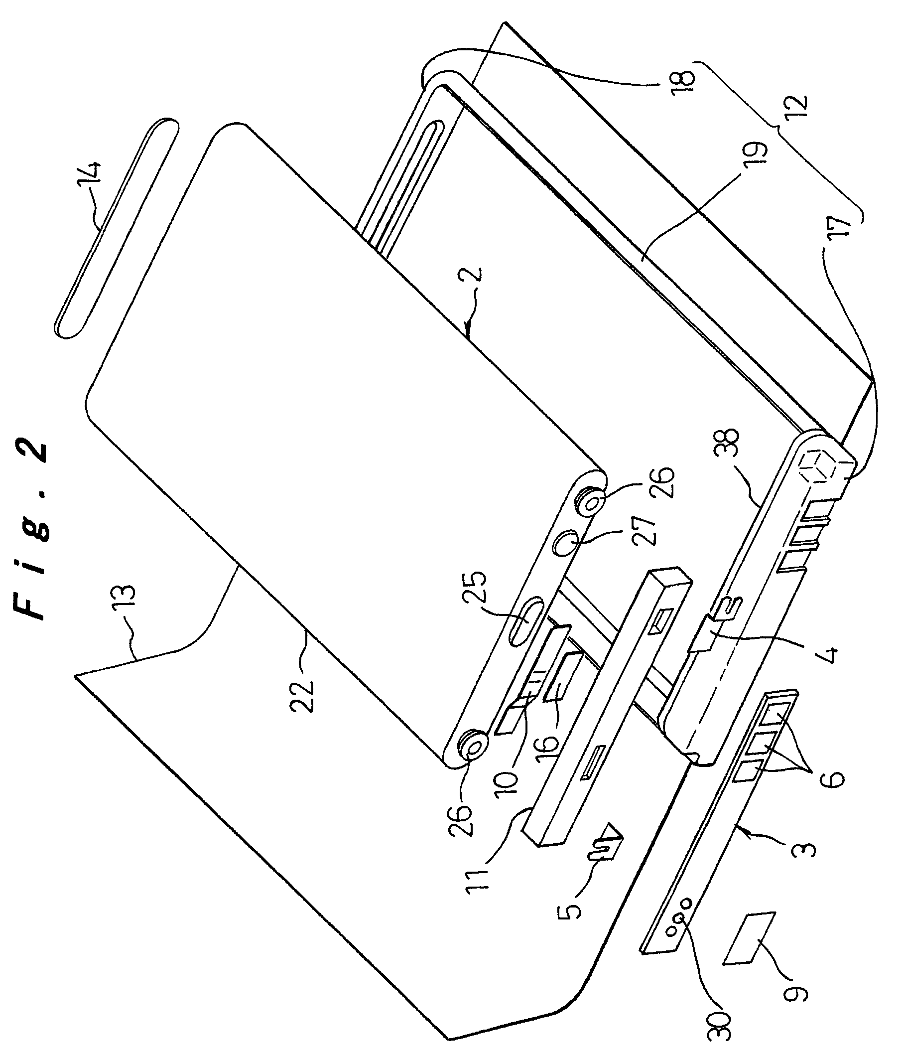
A heat insulation sheet (16) covers a temperature fuse (10) arranged on a sealing plate (23) of a rechargeable battery (2) so as to provide a shield from heat of resin that is filled in a gap between the rechargeable battery (2) and a circuit substrate (3) to form a primary mold (11) and to prevent destruction of the temperature fuse (10) caused by the heat.

Description

TECHNICAL FIELD[0001]The present invention relates to a battery pack in which constituent elements are united by filling with resin to reduce size and improve rigidity so that it is suitable as a power source for portable electronic equipment, and a manufacturing method thereof.BACKGROUND ART[0002]With the remarkable development of small, thin, and high-functionality portable electronic equipment such as mobile phones and PDAs, there is a growing demand for smaller, thinner, and high-capacity batteries as their power source. Lithium ion rechargeable batteries can be designed small and high-capacity, and in particular, flat prismatic types are suitable in making the equipment thinner; they have therefore been increasingly used as the repeatedly usable rechargeable battery for portable electronic equipment.[0003]Because lithium ion rechargeable batteries have high energy density and contain a flammable organic solvent as electrolyte, it is essential to take account of safety measures....

Claims


Application Information

Patent Timeline
Patent Type & Authority Patents(United States)
IPC IPC(8): H01M2/08H01M6/50H01M10/42H01M50/583H01M50/588
CPCH01M2/1061H01M2/34H01M10/4257H01M2/348Y10T29/49114H01M2200/103Y02E60/10H01M50/581Y02P70/50H01M50/588H01M50/583H01M50/20
Inventor KOZU, KATSUMIISHIMARU, TAKESHIOSAWA, YOSHIKIKATAOKA, SATOSHIMORI, IICHIROTORIYAMA, KOICHIMIZUTA, MASAHIROCHIKADA, TATSUHISA
Owner PANASONIC CORP
Why Eureka
Try Eureka