
Method and apparatus for increasing the size of small particles

a technology of small particles and small particles, applied in the field of small particle size increasing methods and equipment, can solve the problems of preventing the understanding of evaluation, preventing the formation of secondary aerosols, and creating flow recirculations in the system

Inactive Publication Date: 2011-07-12
DEKATI
View PDF5 Cites 6 Cited by
  • Summary
  • Abstract
  • Description
  • Claims
  • Application Information

AI Technical Summary

Benefits of technology

[0020]The purpose of the present invention is thus to provide a method and an apparatus for increasing the size of small particles, which method and apparatus avoid the above-mentioned problems and by means of which the small particles in aerosol can be increased large enough to be detected with a detector, and substantially all particles are conveyed to the detector without any loss during conveyance.
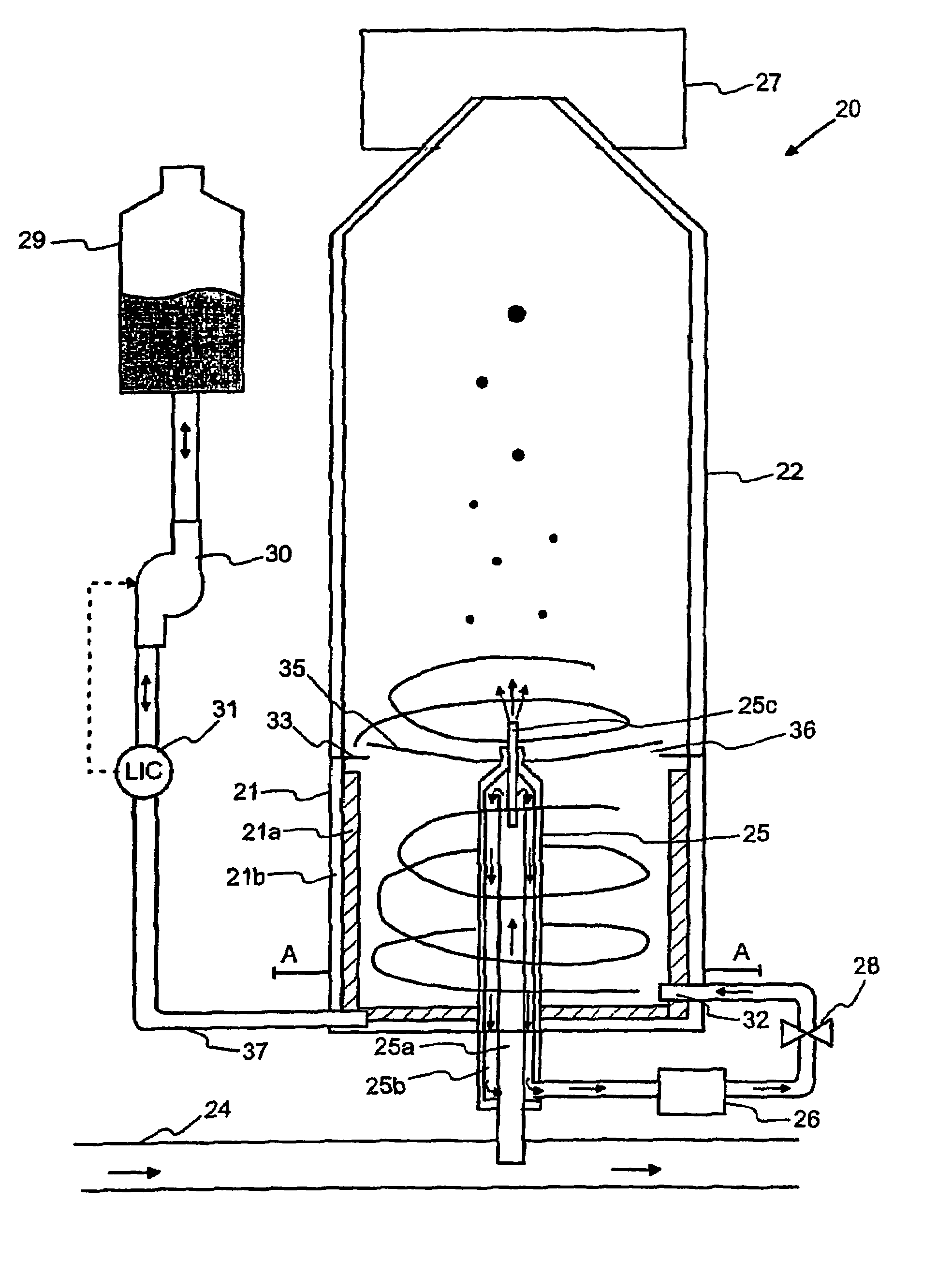
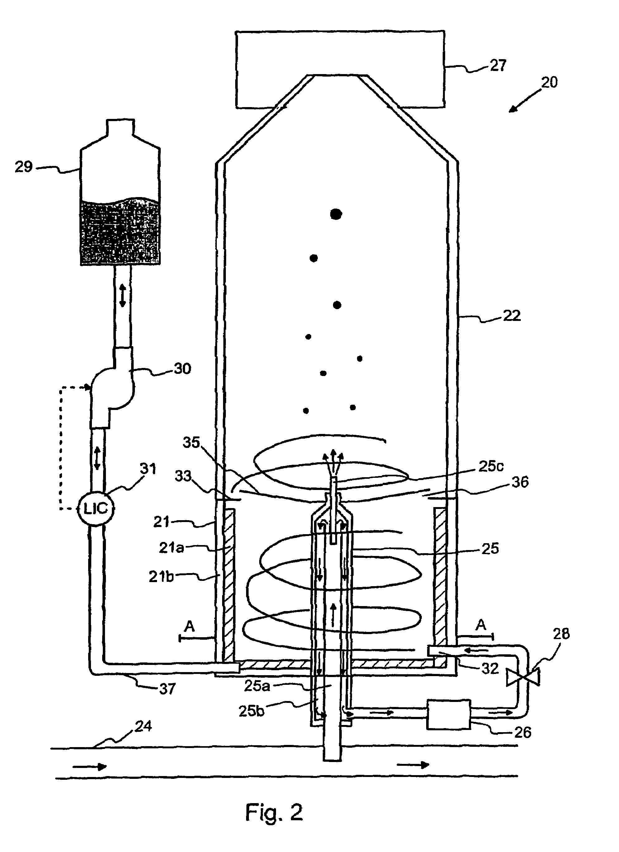
[0021]The invention is based on the idea that the sample flow is introduced to the centre of with vapor saturated sheath flow. Prior to sample flow feeding point, the sheath flow is caused to form a vortex flow, that extends all the way from saturator to condenser and forms a shielding layer between the condenser wall and sample particles, thus preventing the sample particles hitting the walls and making it possible, that even the smallest particles will enter the detector. So there are no losses in the condenser.
[0022]In the apparatus according to the invention, the saturator and the condenser are integrated into one structure in such a manner that the measures of the apparatus, both the height and the width, are decreased and thus the flow delay times are shortened significantly. The condenser is formed in the same structure with the saturator, i.e. it is installed on top of the saturator, as its extension. The division of the aerosol to sheath flow and sample flow takes place in a flow divider, which is known as such from prior art. The cleaned sheath flow is brought to the lower part of the saturator tangentially, creating a turbulent vortex flow around the flow divider. The vortex flow helps the vapor saturation of the sheath flow, because it is in close contact with the liquid impregnated felt elements on the saturator inner lining. Further, because the structure formed by the saturator and the condenser is compact and short, the vortex-flow-effect created in the saturator continues to the condenser as the saturated sheath flow flows upwardly along the saturator and condenser inner surfaces. This means that there is a continuous supersaturated sheath flow upwards against the condenser walls as well. The particle-containing sample flow is introduced to the condenser to the centre of the vortex flow. Because the sample flow is confined near the centerline of the condenser, it encounters high supersaturation levels and negligible losses of the formed droplets to the wall. To assist the formation of the vortex in the condenser, it is possible to attach a vortex generating means in condenser, before the sample feeding point.

Problems solved by technology

The absence of reliable aerosol data prevents understanding of the formation of these secondary aerosols and evaluation of their treatment in chemical transport models.
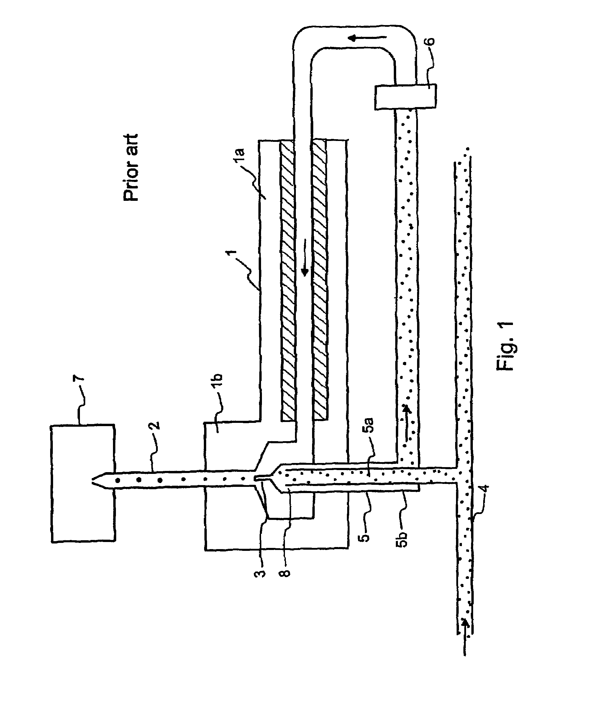
However, there are several problems with the CPC according to FIG. 1.
Another problem is that flow recirculations are created in the system.
Thus, while some grown particles immediately exit the condenser and enter the detector, other particles just circulate inside the condenser and randomly exit at some later time, introducing an exponentially decaying distribution of delays between the time particle enters condenser and when it is detected.
Thus it is impossible to obtain sensitive size distributions.
Also due to long condenser which is needed for particle growth, the ultra small particles in the flow tend to hit the condenser walls, prior reaching the detector, thus causing erroneous results.
Further problem is the long saturator and the large diameter of the felt tube in the saturation section 1a.

Method used


Image

  • Method and apparatus for increasing the size of small particles
  • Method and apparatus for increasing the size of small particles
  • Method and apparatus for increasing the size of small particles

Examples


Embodiment Construction

[0028]FIG. 1 has been explained above, and thus it will not be discussed here any more.

[0029]FIG. 2 shows a CPC apparatus 20, which includes an apparatus for increasing particles according to the invention. The aerosol flow is directed to the apparatus via a channel 24. The aerosol flow flows to a flow divider 25 via an inner channel 25a, whose other end extends inside the channel 24. The flow divider 25 and its operation is substantially the same as the flow divider 5 presented in connection with FIG. 1, which is why it will not be described in more detail in this context.

[0030]The flow divider 25 is placed inside a saturator 21, in the centre of it, so that the midpoint of the bottom of the saturator 21 and the longitudinal axis extending via the center of the cross section of the flow divider 25 are combined. The flow divider 25 extends through the height of the saturator 21 and it ends inside a condenser 22 mounted in connection with the saturator 21. The sheath flow divided in ...


PUM

PropertyMeasurementUnit
diameteraaaaaaaaaa
sizeaaaaaaaaaa
heightaaaaaaaaaa

Abstract

A method and apparatus for increasing the size of small particles for a condensation particle counter, in which method a particle containing aerosol flow is divided into a sample flow and a sheath flow. The sheath flow is filtered, saturated with vapor and formed to a vortex flow in a saturator which vortex-flow continues in a condenser. The sample flow is introduced to the center of the vortex flow of the saturated sheath flow in the condenser for causing the vapor in the saturated sheath flow to condense on the particles in the sample flow thus increasing the size of the particles.

Description

CROSS-REFERENCE TO RELATED APPLICATIONS[0001]This application claims priority to Finnish patent application 20045003 filed 8 Jan. 2004 and is the national phase under 35 U.S.C. §371 of PCT / FI2004 / 050192 filed 22 Dec. 2004.FIELD OF THE INVENTION[0002]The invention relates to a method for increasing the particle size of small particles for a condensation particle counter. The invention also relates to an apparatus for implementing the method.BACKGROUND OF THE INVENTION[0003]Aerosols, that is, suspensions of fine particles in air or gas, are today recognized to play a central role in diverse environmental problems such as climate change, impaired visibility caused by the particles in the atmosphere and eutrofication of unhabited lands. They also have an effect to respiratory diseases. Aerosols are also the sites on which heterogeneous reactions of gaseous trace constituents occur. The sources of each of the major chemical constituents of the aerosols must be known and their role in atm...

Claims


Application Information

Patent Timeline
Patent Type & Authority Patents(United States)
IPC IPC(8): G01N1/00G01N15/06
CPCG01N15/065
Inventor ULEVICIUS, VIDMANTASKULMALA, MARKKUMORDAS, GENRIKMATULEVICIUS, VYTAUTASGRIGORAITIS, VYTAUTASHAMERI, KAARLEAALTO, PASI
Owner DEKATI
Learn More