
Ozone detecting device

a detection device and ozone technology, applied in the direction of optical radiation measurement, instruments, analysis using chemical indicators, etc., can solve the problems of inability to simple measurements, affecting the environment, and affecting the effect of environmental pollution

Inactive Publication Date: 2011-07-12
NIPPON TELEGRAPH & TELEPHONE CORP
View PDF10 Cites 7 Cited by
  • Summary
  • Abstract
  • Description
  • Claims
  • Application Information

AI Technical Summary

Benefits of technology

[0017]In the present invention as explained above, the carrier carries the alkaline substance in addition to the dye selected from the anthraquinone-based dye having a hydroxy group, and the azo dye having a hydroxy group and a sulfurous acid group bonded to a position not adjacent to an azo group. Consequently, the present invention achieves a remarkable effect of simply detecting the cumulative amount of ozone in a gas to be measured.

Problems solved by technology

Presently, NOx, SPM (Suspended Particulate Matter), and photochemical oxidant cause air pollution, and the influence on the environment is regarded as a problem.
For example, the photochemical oxidant mainly containing a strongly acidic substance such as ozone is produced by a photochemical reaction caused by a pollutant such as NOx or hydrocarbon exhausted from factories, offices, and automobiles when the pollutant is irradiated with the sun light, and causes photochemical smog.
Although these measurement methods can measure a slight amount of a gas, i.e., a few ppb of a gas, they have drawbacks that apparatuses are enlarged, complicated, and incapable of simple measurements.
Also, these apparatuses are expensive and require constant setup in order to maintain the accuracy.
In addition, automatic measurements performed by these apparatuses always require electric power and also require periodic calibration (maintenance).
Therefore, enormous costs are required to maintain these apparatuses, and power supplies, temperature-controlled installation environments, and standard gases must be secured.
That is, these apparatuses impose many limitations.
However, these sensors have been developed to evaluate short-time responses, and only few sensors have been developed for monitoring requiring measurement data accumulation.
Furthermore, the above-mentioned sensors have a sensitivity of about sub-ppm, and hence cannot measure concentrations in real environments, e.g., cannot measure 10 ppb of ozone.
This makes comparison difficult when using different sensors.
Unfortunately, this method has also been developed to locally measure a very-short-time concentration in a measurement point.
This makes it difficult to use the method to accumulate measurement data.
This makes cumulative measurement difficult.
Furthermore, this method has problems in accuracy and reproducibility because produced iodine gradually evaporates.
However, this ozone detecting paper has no sufficient sensitivity and cannot well measure a storage amount of 100 ppb×8 hrs as the labor environmental standard.
However, even this technique requires electric power to drive a light source and detector during measurement, and also requires an expensive carrier, i.e., porous glass.

Method used


Image

  • Ozone detecting device
  • Ozone detecting device
  • Ozone detecting device

Examples


embodiment 1

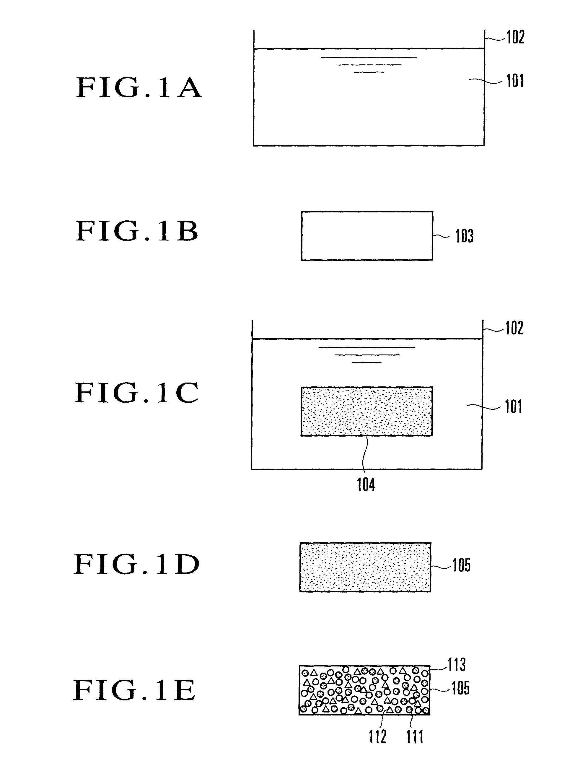
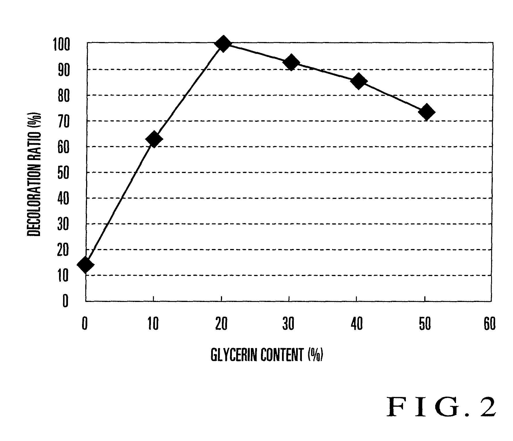
[0029]First, Embodiment 1 of the present invention will be explained. FIGS. 1A to 1E are views of steps for explaining an example of an ozone detecting device manufacturing method according to Embodiment 1 of the present invention. First, as shown in FIG. 1A, a vessel 102 containing a detector solution 101 is prepared. The detector solution 101 is an aqueous solution prepared by dissolving a dye made of alizarin (1,2-dihydroxyanthraquinone: C14H8O2(OH)2) and a humectant made of glycerin (C3H8O3), and alkalized by dissolving a base. The content of the humectant is about 20 wt %.

[0030]For example, the detector solution 101 is prepared by dissolving 0.025 g of alizarin in 25 ml of an aqueous solution in which sodium hydroxide as a base that is an alkaline substance is dissolved at a concentration of 0.1 mol / liter, and adding 10 g of glycerin and water to the solution such that the total amount is 50 g. Alizarin is an anthraquinone-based dye (dyestuff). The detector solution 101 prepare...

embodiment 2

[0052]Another ozone detecting device according to Embodiment 2 of the present invention will be explained below. In this embodiment, the case in which Alizarin Red S (also called Mordant Red 3) was used as an anthraquinone-based dye instead of alizarin described above will be explained. First, 0.03 g of Alizarin Red S are dissolved in 25 ml of an aqueous 0.1-mol / liter sodium hydroxide solution, and water is added to the solution such that the total amount is 50 g, thereby forming detector solution G. The formed detector solution does not contain glycerin as a humectant. Ozone detecting device G is formed by using detector solution G in the same manner as described above. The color of ozone detecting device G thus formed is purple.

[0053]Also, 0.03 g of Alizarin Red S are dissolved in 25 ml of an aqueous 0.1-mol / liter sodium hydroxide solution, and 5 g of glycerin as a humectant and water are added to the solution to make 50 g, thereby forming detector solution H. Ozone detecting devi...

embodiment 3

[0093]The case in which ethyleneglycol was used as a humectant will be explained below. First, 0.025 g of alizarin are dissolved in 25 ml of an aqueous 0.1-mol / liter sodium hydroxide solution, and 5 g of ethyleneglycol as a humectant and water are added to the solution to make 50 g, thereby forming detector solution M. Ozone detecting device M is formed by using detector solution M in the same manner as described above. The color of ozone detecting device M thus formed is purple.

[0094]Also, 0.025 g of alizarin are dissolved in 25 ml of an aqueous 0.1-mol / liter sodium hydroxide solution, and 10 g of ethyleneglycol as a humectant and water are added to the solution to make 50 g, thereby forming detector solution N. Ozone detecting device N is formed by using detector solution N in the same manner as described above. The color of ozone detecting device N thus formed is purple.

[0095]In addition, 0.025 g of alizarin are dissolved in 25 ml of an aqueous 0.1-mol / liter sodium hydroxide solu...


PUM


Abstract

An aqueous solution is formed by dissolving a dye made of alizarin and a humectant made of glycerin, and alkalized by dissolving a base (alkaline substance), thereby preparing a detector solution (101) in which the content of the humectant is about 20 wt %. An impregnated carrier (104) impregnated with the detector solution (101) is formed by dipping for 30 sec a sheet-like carrier (103) made of cellulose filter paper in the detector solution (101) so that the carrier (103) is impregnated with the detector solution (101). The impregnated carrier (104) is pulled up from the detector solution (101), and dried in dry nitrogen by evaporating a solvent such as water contained in the impregnated carrier (104), thereby forming an ozone detecting device (105).

Description

[0001]The present patent application is a non-provisional application of International Application No. PCT / JP2007 / 069309, filed Oct. 2, 2007.TECHNICAL FIELD[0002]The present invention relates to an ozone detecting device for detecting ozone existing in a gas such as the air by a discoloring reaction.BACKGROUND ART[0003]Presently, NOx, SPM (Suspended Particulate Matter), and photochemical oxidant cause air pollution, and the influence on the environment is regarded as a problem. For example, the photochemical oxidant mainly containing a strongly acidic substance such as ozone is produced by a photochemical reaction caused by a pollutant such as NOx or hydrocarbon exhausted from factories, offices, and automobiles when the pollutant is irradiated with the sun light, and causes photochemical smog.[0004]In Japan, environmental standards are set for these substances, and general environmental air measurement stations in various places measure the substances. For example, an environmental...

Claims


Application Information

Patent Timeline
Patent Type & Authority Patents(United States)
IPC IPC(8): G01J1/48
CPCG01N21/783G01N31/225Y10T436/206664
Inventor MARUO, YASUKOMIWA, TAKASHINAKAMURA, JIROKUNIOKA, TATSUYA
Owner NIPPON TELEGRAPH & TELEPHONE CORP
Learn More