
Worm gear unit and method of producing same

a technology of worm gear and gear teeth, which is applied in the direction of gear teeth, gear rings, other domestic objects, etc., can solve the problems of costly products of worm gear units, and achieve the effect of satisfying mechanical strength

Inactive Publication Date: 2011-07-19
HITACHI LTD
View PDF16 Cites 12 Cited by
  • Summary
  • Abstract
  • Description
  • Claims
  • Application Information

AI Technical Summary

Benefits of technology

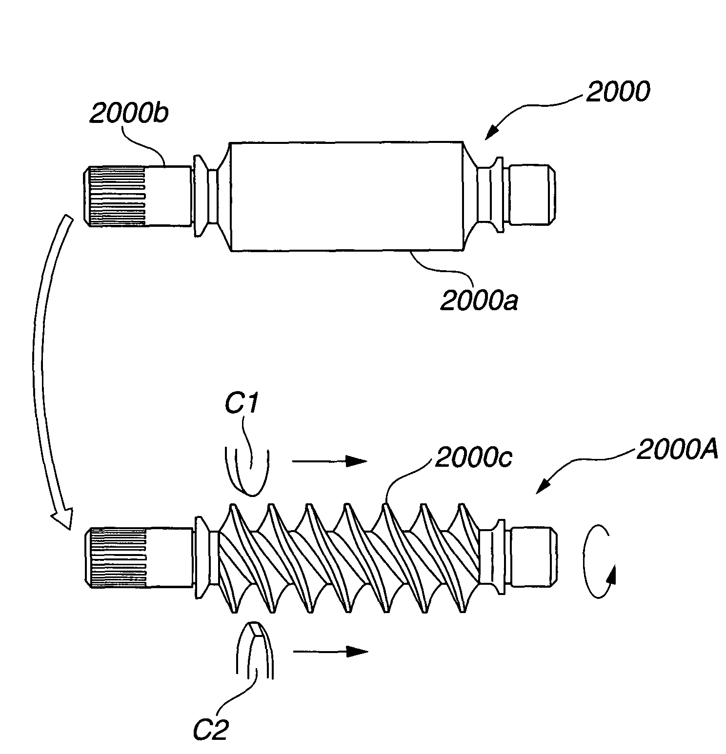
The present invention provides a worm gear unit of Niemann type that exhibits a satisfied mechanical strength and can be produced without need of a highly advanced thread cutting technique. The worm gear unit comprises a worm wheel and a worm shaft, which are meshed together. The meshed engagement between the teeth of the worm wheel and the helical tooth ridge of the worm shaft is represented by a characteristic graph that shows a relation between an allowable error of maximum meshing position and a radius ratio between the first and second radii of curvature. The method of producing the worm wheel involves preparing a circular plate blank and cutting it to produce teeth with a roundly convex outer surface that is shaped to be engaged with the roundly concave outer surface of the helical tooth ridge of the worm shaft. The method of producing the worm shaft involves preparing a cylindrical blank, cutting its outer surface to form the helical tooth ridge, and applying a surface finish process to it without applying a heat treatment.

Problems solved by technology

However, the worm shaft and worm wheel of such Niemann type are complicated in construction and shape, and thus, production of such shaft and wheel needs a highly advanced thread cutting technique, which has thus brought about costly products of the worm gear units.

Method used


Image

  • Worm gear unit and method of producing same
  • Worm gear unit and method of producing same
  • Worm gear unit and method of producing same

Examples


Embodiment Construction

[0033]In the following, the present invention will be described in detail with the aid of the accompanying drawings.

[0034]For ease of understanding, various directional terms, such as, right, left, upper, lower, rightward and the like are used in the following description. However, such terms are to be understood with respect to only the drawing or drawings in which a corresponding part or portion is shown. Throughout the specification, substantially same parts or portions are designated by the same reference numerals.

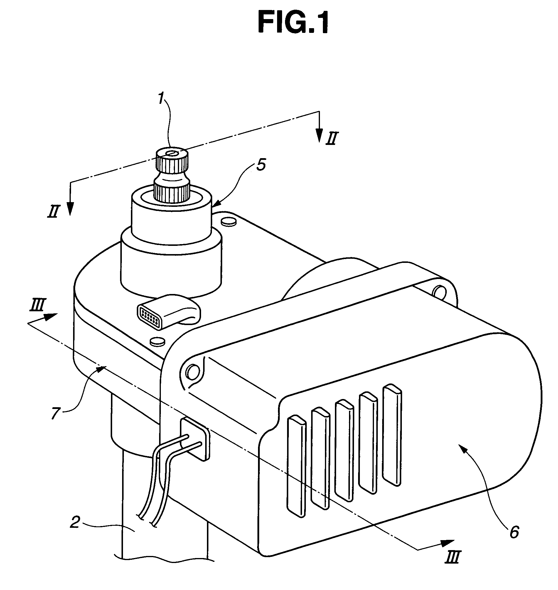
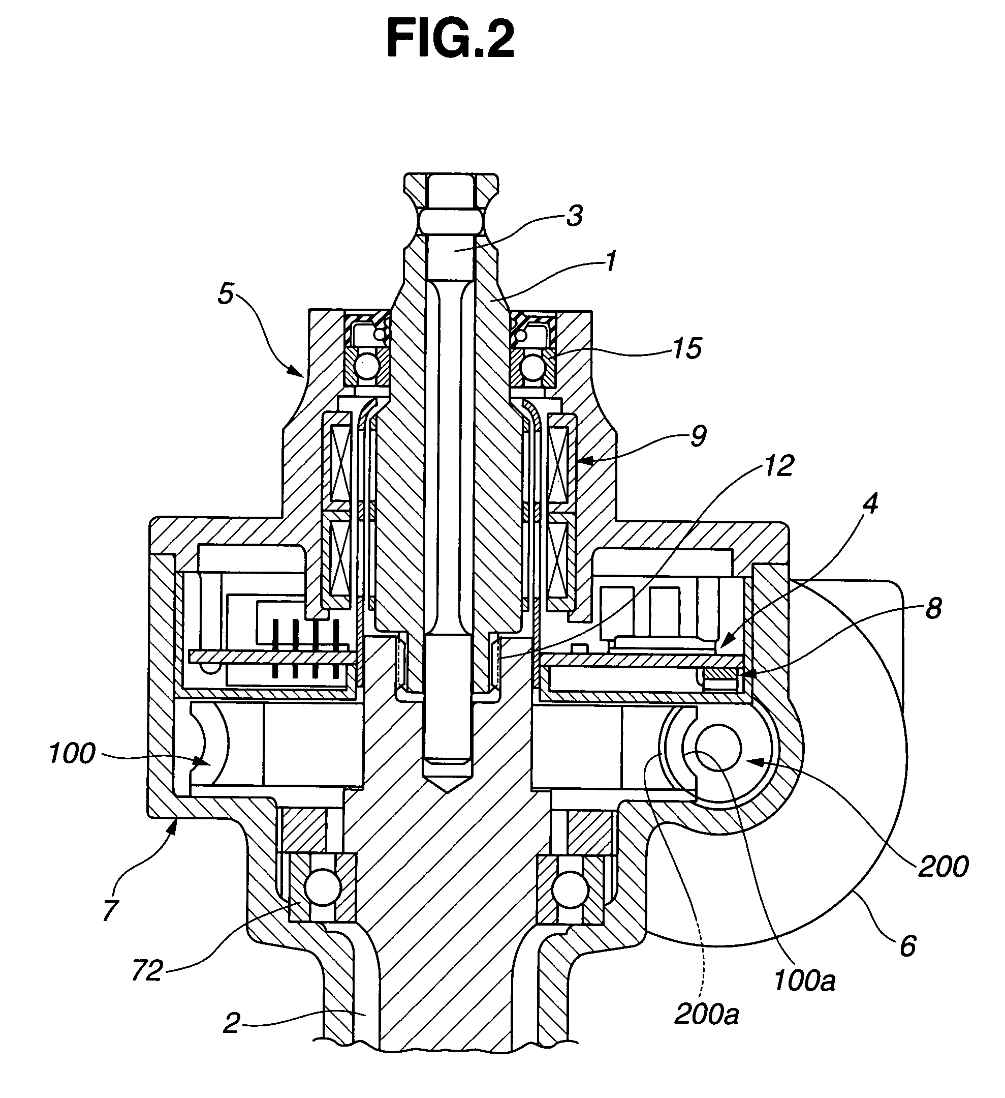
[0035]Referring to FIGS. 1 to 3, there is shown an electric power steering device of a motor vehicle in which a worm gear unit of the present invention is practically installed.

[0036]For clarifying the feature of the worm gear unit of the invention, the electric power steering device will be briefly described with the aid of FIGS. 1 to 3.

[0037]As shown in these drawings, particularly in FIGS. 2 and 3, the electric power steering device comprises a motor housing 6, a wo...


PUM

PropertyMeasurementUnit
radius of curvatureaaaaaaaaaa
radius ratioaaaaaaaaaa
mechanical strengthaaaaaaaaaa

Abstract

By finding a range of an allowable error of maximum meshing position of a worm shaft in an axial direction relative to a worm wheel, that is higher than that of a worm shaft of a conventional worm gear unit, a worm gear unit of the present invention is provided.

Description

BACKGROUND OF INVENTION[0001]1. Field of the Invention[0002]The present invention relates in general to a worm gear unit that includes mutually meshed worm shaft and worm wheel and a method of producing the same, and more particularly a Niemann type worm gear unit and a method of producing the same. The Niemann type worm gear unit comprises a Niemann type worm shaft and a Niemann type worm wheel.[0003]2. Description of the Related Art[0004]Various worm gear units have been hitherto proposed and put into practical use particularly in the field of motor vehicles. The worm gear unit is sometimes called just “worm gear”.[0005]One of them is disclosed in Japanese Laid-open Utility Model Application (Jikkaihei) 4-56250. The worm gear unit shown in the publication is of a Niemann type that comprises a Niemann type worm shaft and a Niemann type worm wheel which are operatively engaged or meshed when in use. The worm shaft and worm wheel of such type have arc-shaped continuous ribs (or helic...

Claims


Application Information

Patent Timeline
Patent Type & Authority Patents(United States)
IPC IPC(8): B21D53/28F16H3/08
CPCB23F11/00B23F13/00B23F17/001B23P15/14Y10T29/49469Y10T74/19828Y10T29/49476Y10T74/19219
Inventor SHIINO, KOHTAROFUKUDA, YUSUKE
Owner HITACHI LTD
Learn More