Engine starter having shift lever with lubricant-blocking wall

a technology of shifting lever and lubricant, which is applied in the direction of engine starters, machines/engines, power operated starters, etc., can solve the problems of premature exhaustion, difficult to suppress wear and thermal deformation of the lever ring, and a large friction between the ring member and the ring portion of the shifting member can be considerably reduced, and suppress wear and thermal deformation of the ring portion over a long time period

Inactive Publication Date: 2011-07-19
DENSO CORP
View PDF22 Cites 7 Cited by
  • Summary
  • Abstract
  • Description
  • Claims
  • Application Information

AI Technical Summary

Benefits of technology

[0011]Since the ring member is rotatable relative to the pinion carrier, in an overrun state where torque generated by the engine is transmitted from the ring gear to the pinion, the ring member will lag the pinion and the pinion carrier in rotational speed due to the viscosity of the lubricant which has flowed out of the recess of the ring portion of the shifting member and adhered to the surface of the ring member. Consequently, the difference in rotational speed between the ring member and the ring portion of the shifting member will accordingly be small. Further, by virtue of the lubricating function of the lubricant, the friction between the ring member and the ring portion of the shifting member can be considerably decreased. As a result, both wear and thermal deformation of the ring portion of the shifting member due to friction can be effectively suppressed. Moreover, with the lubricant blocking member, the lubricant filled in the recess of the ring portion of the shifting member can be prevented from being prematurely exhausted, thus making it possible to suppress wear and thermal deformation of the ring portion over a long time period.

Problems solved by technology

Consequently, the grease filled in the groove 111 can be prematurely exhausted, thus making it difficult to suppress wear and thermal deformation of the lever ring 110 over a long time period.

Method used


Image

  • Engine starter having shift lever with lubricant-blocking wall
  • Engine starter having shift lever with lubricant-blocking wall
  • Engine starter having shift lever with lubricant-blocking wall

Examples


Embodiment Construction

[0018]One preferred embodiment of the present invention will be described hereinafter with reference to FIGS. 1-3.

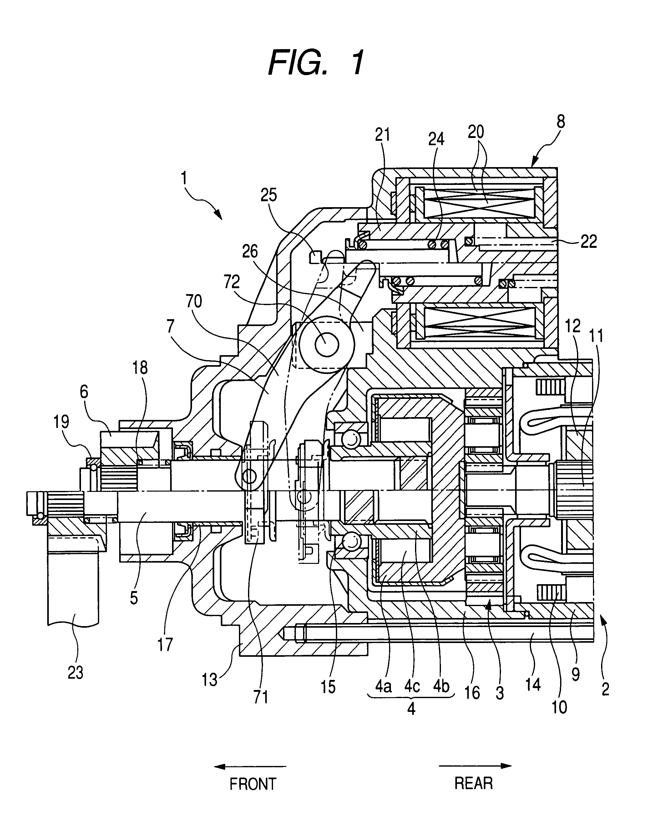
[0019]FIG. 1 shows the overall structure of a starter 1 according to an embodiment of the invention, which is designed to start an internal combustion engine (not shown) of a motor vehicle.

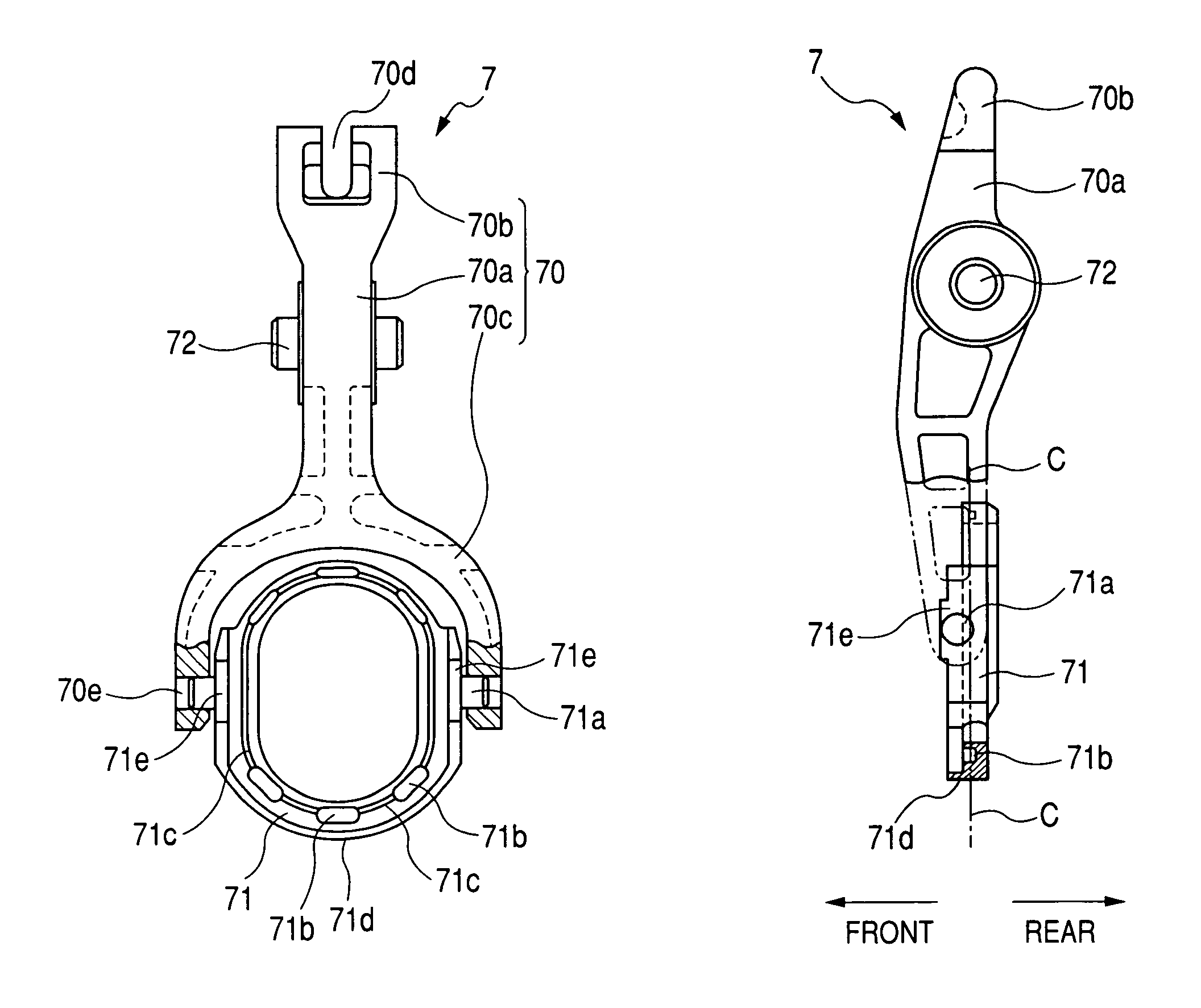
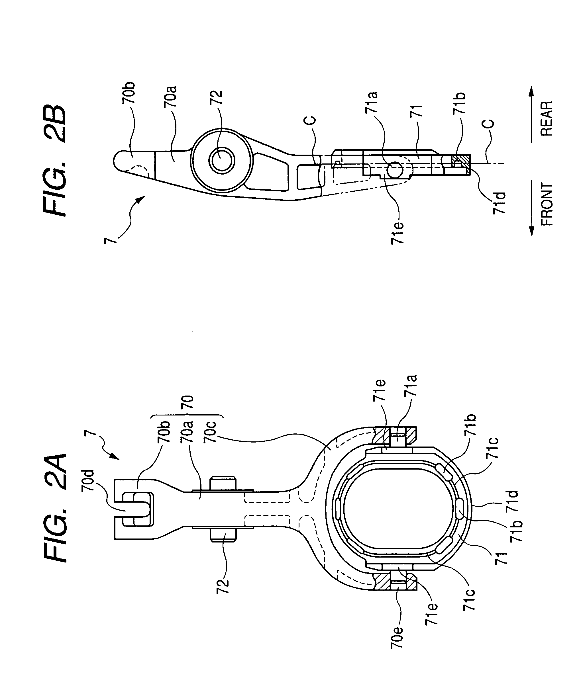
[0020]As shown in FIG. 1, the starter 1 includes a motor 2 that generates torque, a speed reduction gear 3 for reducing the rotational speed of the motor 2, a clutch 4, an output shaft 5 that is linked to the speed reduction gear 3 via the clutch 4, a pinion 6 carried on the output shaft 5, a shift lever 7, and a solenoid or electromagnetic switch 8 that operates supply of electric power to the motor 2 and causes the shift lever 7 to shift the output shaft 5 in the axial direction.

[0021]It should be noted that in FIG. 1, the upper parts of some components with respect to the axis of the output shaft 5 or the axis of the solenoid switch 8 show those components in a first starter state,...


PUM


Abstract

A starter includes a motor, a pinion, a pinion carrier carrying the pinion, a ring member provided on the pinion carrier, a shifting member, and a lubricant blocking member. The ring member is rotatable relative to the pinion carrier and restricted in axial movement toward the pinion. The shifting member has a ring portion that is arranged on the pinion carrier with the ring member interposed between the ring portion and the pinion. The ring portion has an axial end face that has a recess for receiving lubricant and is covered by the ring member. The shifting member is configured to shift, by pushing the ring member with the ring portion, the pinion in the axial direction, thereby bringing the pinion into mesh with a ring gear of an engine. The lubricant blocking member blocks the lubricant from being scattered due to rotation of the pinion carrier with the pinion.

Description

CROSS-REFERENCE TO RELATED APPLICATION[0001]This application is based on and claims priority from Japanese Patent Application No. 2006-297960, filed on Nov. 1, 2006, the content of which is hereby incorporated by reference in its entirety into this application.BACKGROUND OF THE INVENTION[0002]1. Technical Field of the Invention[0003]The present invention relates to starters having a pinion and a shift lever that shifts the pinion into mesh with a ring gear of an engine.[0004]2. Description of the Related Art[0005]Japanese Patent First Publication No. 2007-85317 discloses an engine starter that includes a low-cost shift lever, which is made of resin, and has an improved structure for effectively suppressing wear and thermal deformation of the shift lever.[0006]More specifically, as shown in FIG. 4, the starter includes an output shaft 100, a pinion 140 provided on the output shaft 100, the resin-made shift lever that has a lever ring 110 provided on the output shaft 100, a pair of ri...

Claims


Application Information

Patent Timeline
Patent Type & Authority Patents(United States)
IPC IPC(8): F02N15/06F02N15/02
CPCF02N15/067F02N15/023Y10T74/137Y10T74/13F02N2250/08
Inventor HASEGAWA, YOUICHIIMANISHI, TOMOYA
Owner DENSO CORP
Why Eureka
Try Eureka