

Vacuum cooking or warming appliance
a heating appliance and vacuum technology, applied in the field of vacuum heating appliances, can solve the problems of reducing the thermal recovery time of the griddle, and achieve the effects of reducing the thermal recovery time, reducing the heating time, and consuming less energy
- Summary
- Abstract
- Description
- Claims
- Application Information
AI Technical Summary
Problems solved by technology
Method used
Image

Examples
examples of invention
Example 1
Popcorn Maker
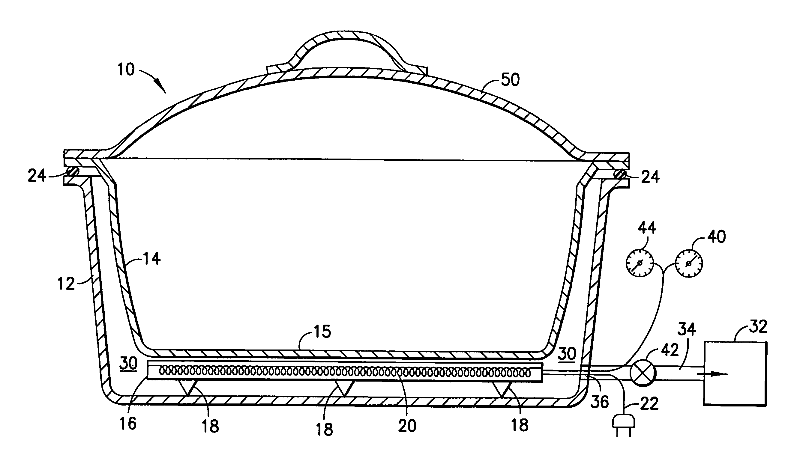
[0033]An apparatus 10, as depicted in FIG. 1, with an outer shell 12 of approximately 10″ circular diameter is fitted with a high temperature gasket 24 of a compressible nature around the top rim. A strong and well-insulated lid 50 is placed on the rim without the presence of a food vessel 14 and the apparatus is turned on for preheating. The preset temperature (350° F.) and vacuum (23 inches Hg) are quickly achieved and the vacuum pump 32 and resistance heater 20 automatically shut off. The apparatus sits in an idle state at temperature and under vacuum until cooking is desired. At that time, a food vessel 14 has ½ cup of vegetable oil and 1 cup of popcorn placed therein. The vacuum is vented to atmosphere by way of solenoid valve 42, the lid 50 is removed and the food vessel 14 with the oil and popcorn therein is placed on the vacuum seal 24. The vacuum pump 32 is then restarted. The lid that was previously on the outer shell during preheat is now placed on t...
example 2
Griddle
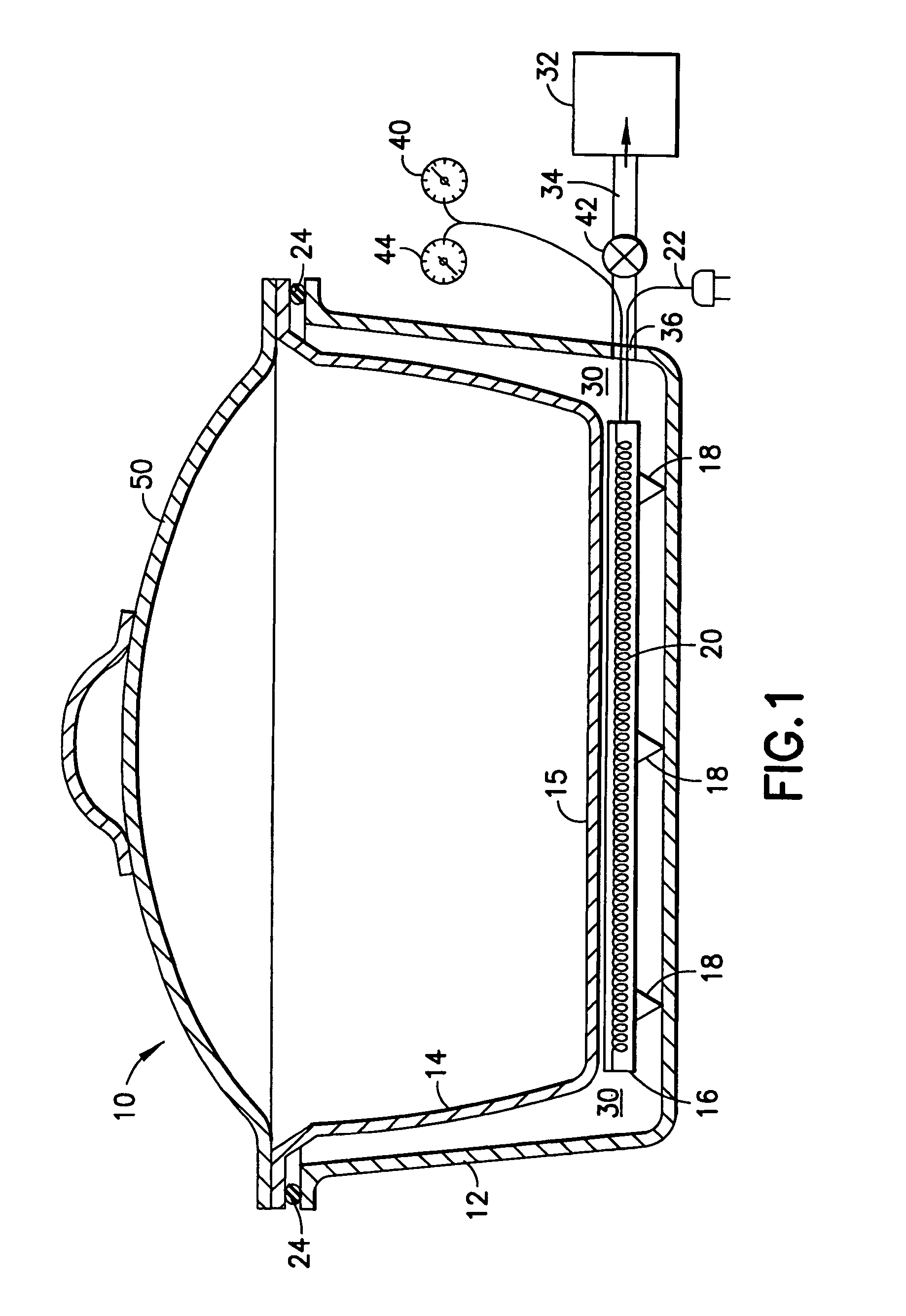
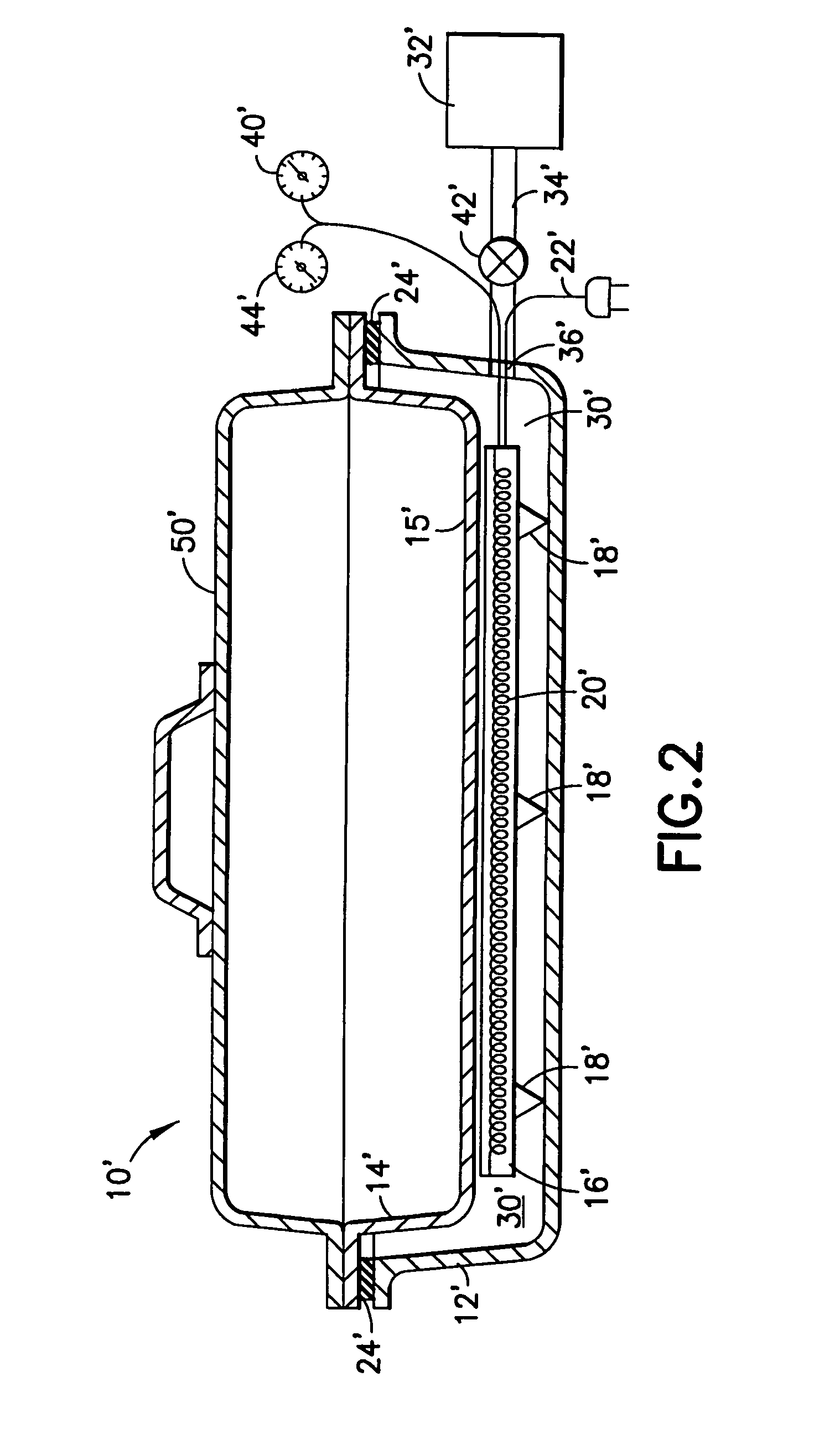
[0034]The apparatus depicted in FIG. 2 with reference to Example 2 has generally the same structural elements as the apparatus shown and described in FIG. 1. Accordingly, like elements will be designated with the same numerals, but with prime symbols added in FIG. 2.
[0035]As shown in FIG. 2, an apparatus 10′ of the same generic construction as Example 1, but with an outer shell 12′ of rectangular shape, for example, measuring 12 inches by 16 inches, is fitted with a strong, well-insulated lid 50′ that will withstand the atmospheric pressure without collapsing under vacuum during the preheat period. The plane of the heat sink 16′ is only ⅛″ below the plane of the top of the vacuum seal 24′ in its uncompressed state. The apparatus reaches preset heat and vacuum levels and idles. When desired, the vacuum is broken and the lid 50′ is removed and replaced with a flat thin sheet of stainless steel or titanium which acts as a food vessel 14′ in the form of a griddle cooktop 15′. Atm...
example 3
Two-Sided Grill / Waffle Maker
[0036]Two outer shells (not shown, but similar in concept to shell 16) are attached by a hinge in a “clam shell” type of arrangement. Both halves are equipped with a heat sink 16 and a port 36 to a vacuum pump 32. When the two halves are closed on each other, high temperature seals 24 around the perimeter of each shell contact the other. In other words, the clam shell is closed and the vacuum seal of each half contacts the other half. Vacuum is established and the heat sinks 16 in each half are preheated to a desired temperature. When desired, the vacuum is vented to atmosphere and the claim shell is opened. Grill vessel plates 14 which may include cast aluminum with a non-stick coating are placed against the vacuum seals 24 and vacuum is established in each of the two halves. When the clam shell is closed again, it may be used as a waffle maker, a two-sided grill, a panini press, or any other two-sided heat source application. The usage is determined by ...
PUM
| Property | Measurement | Unit |
|---|---|---|
| temperature | aaaaa | aaaaa |
| thickness | aaaaa | aaaaa |
| thickness | aaaaa | aaaaa |
Abstract
Description
Claims
Application Information