Fish processing device

a processing device and fish technology, applied in fish processing, slaughtering devices, butchering, etc., can solve the problems of salmon, high labor intensity, and device performing unwanted operations, and achieve rapid and efficient processing, convenient use, and superior corrosion resistance.

Inactive Publication Date: 2011-07-19
RICHARD BASS PTY LTD
View PDF13 Cites 9 Cited by
  • Summary
  • Abstract
  • Description
  • Claims
  • Application Information

AI Technical Summary

Benefits of technology

[0014]a mechanism for resetting the device after the processing of a fish, wherein the resetting mechanism is in communication with the trigger and wherein actuation of the mechanism by the trigger facilitates:
[0078]With devices according to the invention, fish to be processed can be rapidly and efficiently processed with minimal risk of injury to an operator since operation of devices can be automated. An additional advantage of devices according to the invention is that the external appearance of the animal or fish is not affected by the killing process. This is particularly important for sale of whole fish. The quality of fish is also enhanced through more rapid and humane killing at the point of harvest.

Problems solved by technology

In some circumstances, however, the device performs an unwanted operation which is known in the trade as “hammering”.
As a consequence the processed fish suffers multiple piston strikes, resulting in damage to the vendible portions of the fish.
Fish, such as salmon, require labour intensive preparation before sale.
Manual bleeding is a labour intensive process and is therefore a rate limiting step in the overall processing of the fish.
A fortiori because of the speed with which fish are stunned by the device there is a considerable lag between stunning and bleeding which may affect the quality and therefore sale price of the meat.
These tasks are also labour intensive and costly due to the number of man hours required to carry them out.

Method used


Image

  • Fish processing device
  • Fish processing device
  • Fish processing device

Examples


Embodiment Construction

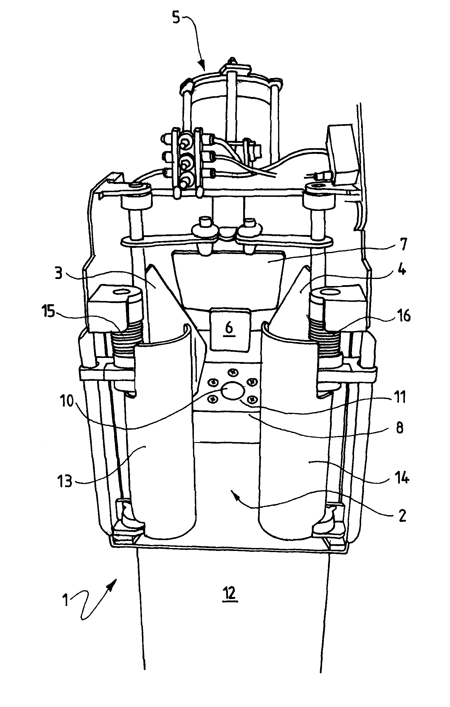
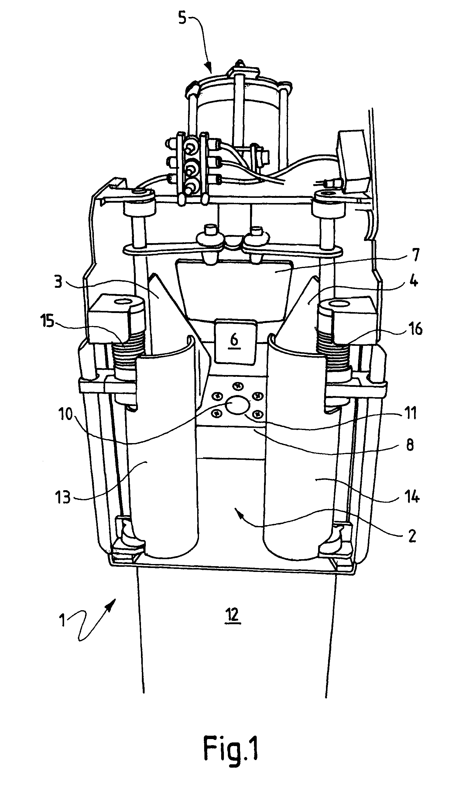
[0095]With reference to FIG. 1, there is shown device 1, when at the firing position, comprising channel 2, vertical guide plates 3 and 4, gun assembly 5, trigger assembly 6, forehead plate 7, and chin plate 8. A pneumatic blade assembly 9, not shown in the drawing but to be described below is fitted to chin plate 8 and wherein blade 10 of said assembly enters channel 2 via aperture 11. Pneumatic blade assembly 9 is contained within cover 12. At the entry to channel 2 there is shown feeder plates 13 and 14 that are pivotally mounted to said channel and biased to return to the closed position by the action of springs 15 and 16.

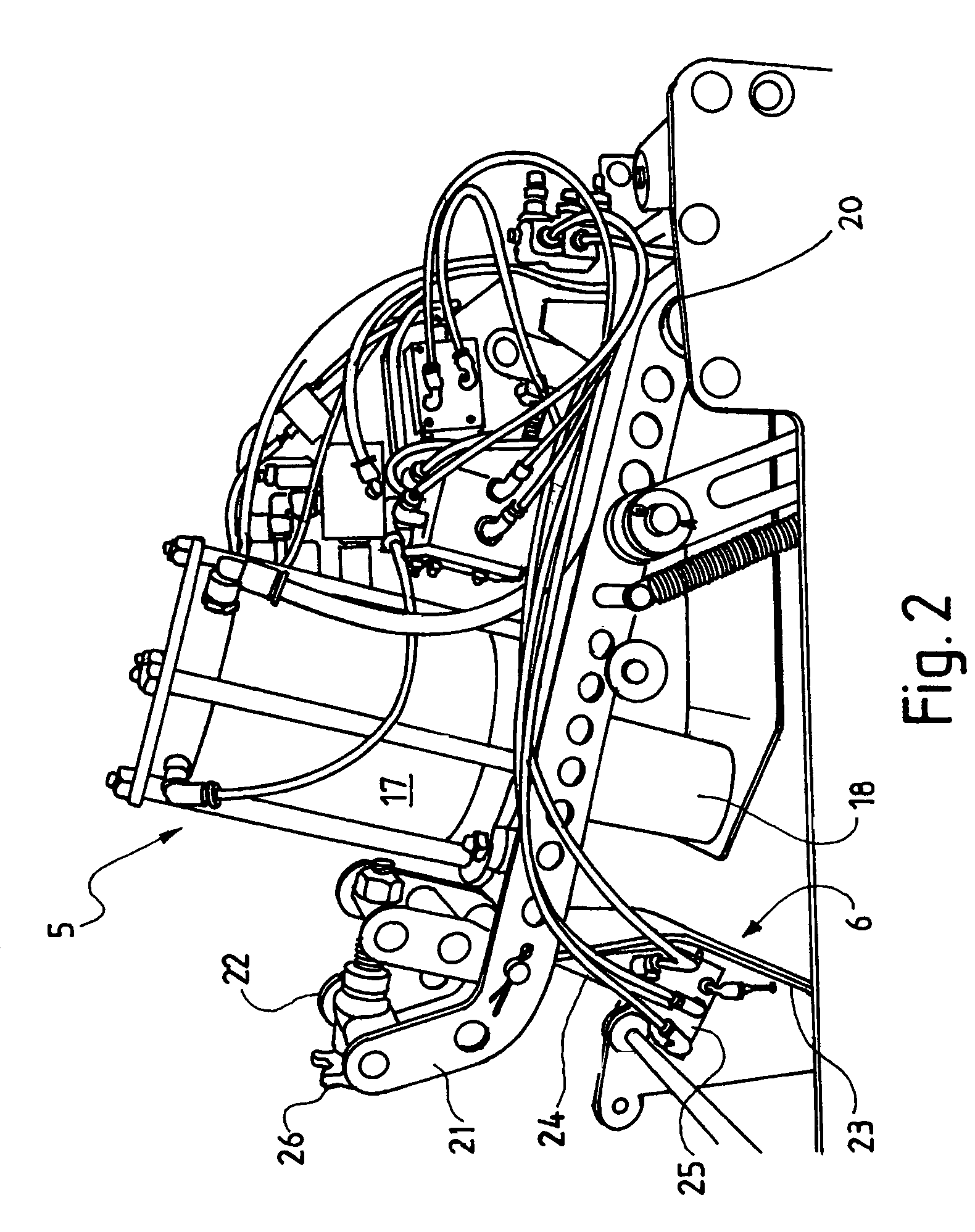
[0096]FIG. 2 provides a side view of gun assembly 5 when at a retracted position—i.e. post firing. Gun assembly 5 has an pneumatic cylinder 17 and a sleeve 18 from which a striker 19 (not shown) extends for stunning a fish on firing. The assembly is pivotally mounted to a shaft 20 across channel 2 by a pair of rails 21 and 22. Trigger assembly 6 is pivotally mo...


PUM


Abstract

A device for processing fish, the device comprising: an open channel through which a fish can pass; a fish processing means associated with the channel; a vertical guide plate pivotally mounted on each side of the channel, having a firing position and a retracted position; a mechanism for moving the fish processing means from a (“firing position”) to a position which allows passage of the fish through the channel after processing (“retracted position”); a mechanism for pivoting each guide plate between the firing and retracted positions (“guide plate pivot mechanism”); a trigger that when contacted by the head of the fish activates the fish processing means; and a mechanism for resetting the device after the processing of a fish, wherein the resetting mechanism is in communication with the trigger and wherein actuation of the mechanism by the trigger facilitates: activation of the fish processing means; movement of the fish processing means and guide plates from their respective firing positions to their respective retracted positions; return of the fish processing means and the vertical guide plates to their respective firing positions after they have attained their retracted positions; and priming of the at least one fish processing means.

Description

TECHNICAL FIELD[0001]The invention described herein relates to devices and methods for processing fish. In particular, the invention is directed to a device and method for the automated processing of fish although the scope of the invention is not necessarily limited thereto.BACKGROUND ART[0002]A pneumatically-powered device suitable for stunning fish is described in International Application No. PCT / AU2005 / 000412 (Publication No. WO 2005 / 091558) by the present applicant. This device can be efficiently used for the stunning of large numbers of fish in an automatic, flow-through fashion and is incorporated herein by cross reference.[0003]The operating principle of the stunning device according to the invention described in WO 05 / 091558 involves the killing of the fish by a blow to the head that is administered by the piston of the gun. Activation of the piston results from the head of the fish contacting the trigger. The trigger and piston are configured such that when the piston is ...

Claims


Application Information

Patent Timeline
Patent Type & Authority Patents(United States)
IPC IPC(8): A22B3/00
CPCA22B3/083A22B3/08A22C25/08
Inventor BASS, RICHARD
Owner RICHARD BASS PTY LTD
Why Eureka
Try Eureka