Arrangement and method for utilizing the heat of waste air for heating the bilge area of aircraft

a technology of waste air and bilge area, which is applied in the direction of aircraft crew accommodation, energy-saving board measures, transportation and packaging, etc., can solve the problems of correspondingly higher expenditure for thermal insulation of areas, and only possible additional heating of bilge area with hot air flow

Inactive Publication Date: 2011-07-19
AIRBUS OPERATIONS GMBH
View PDF31 Cites 11 Cited by
  • Summary
  • Abstract
  • Description
  • Claims
  • Application Information

AI Technical Summary

Benefits of technology

[0007]An exemplary embodiment of the present invention is believed to provide for an improved, effective heating of the bilge area without recirculating the more polluted air from the bilge area such that the expenditure for the thermal insulation of the bilge area can be reduced.
[0008]It is believed that an arrangement of air supply and air discharge pipes may make it possible to effectively utilize any waste air heat flow available in the aircraft (e.g., recirculated cabin air, the hot air flow of the air-conditioning system of the aircraft, waste air from lavatories and galleys or waste air from the cooling of electric consumers) for heating air drawn in from the bilge area with the aid of a heat transfer unit. The drawn-in and thusly heated air is then at least partially returned to the bilge area, wherein the quantitative air balance in the bilge area is not negatively affected, i.e., the quantity of heated air returned to the bilge area is smaller than or equal to the air quantity drawn in from the bilge area. The heated air that is not returned into the bilge area can be directly discharged from the aircraft fuselage in the form of an undesirable waste heat air flow by means of a pressure control valve.
[0009]This may minimize the risk of recirculating air from the bilge area, e.g., into cargo compartments, underfloor areas or cabin areas, during the heating of the bilge area, and only a low expenditure is required for the thermal insulation of the bilge area. The solution according to the invention simultaneously provides improved comfort for underfloor areas and cargo compartments.

Problems solved by technology

This means that a correspondingly higher expenditure is required for the thermal insulation of areas that lie directly adjacent to the bilge area, e.g., cargo compartments and underfloor areas.
In systems used so far, the additional heating of the bilge area with a hot air flow consequently is only possible as long as no recirculation takes place from the bilge area into the cargo compartments, underfloor areas or cabin areas.

Method used


Image

  • Arrangement and method for utilizing the heat of waste air for heating the bilge area of aircraft
  • Arrangement and method for utilizing the heat of waste air for heating the bilge area of aircraft
  • Arrangement and method for utilizing the heat of waste air for heating the bilge area of aircraft

Examples


Embodiment Construction

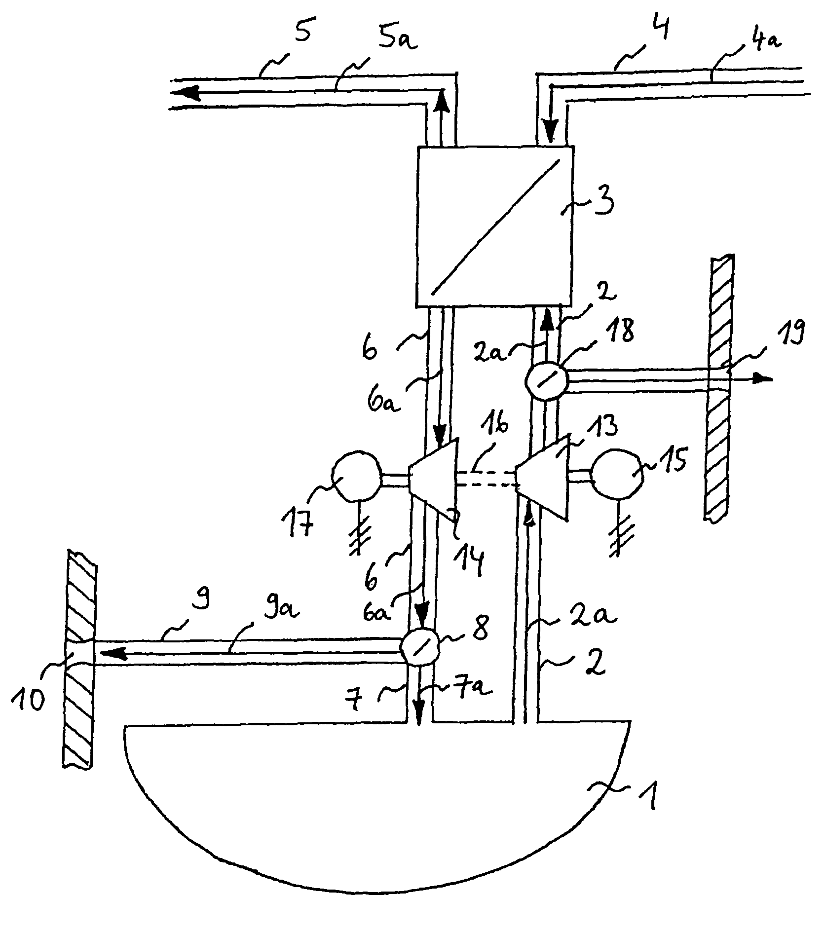
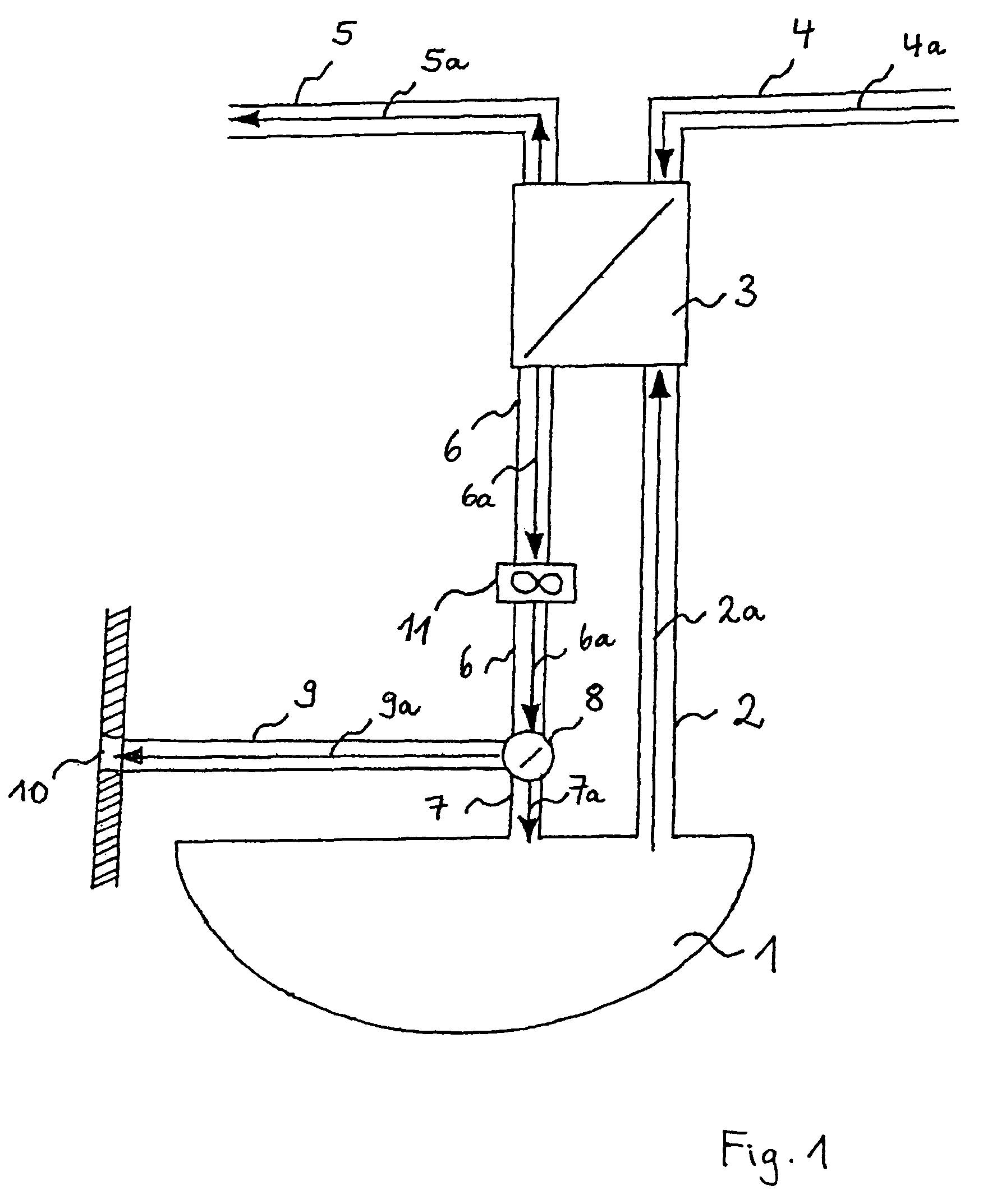
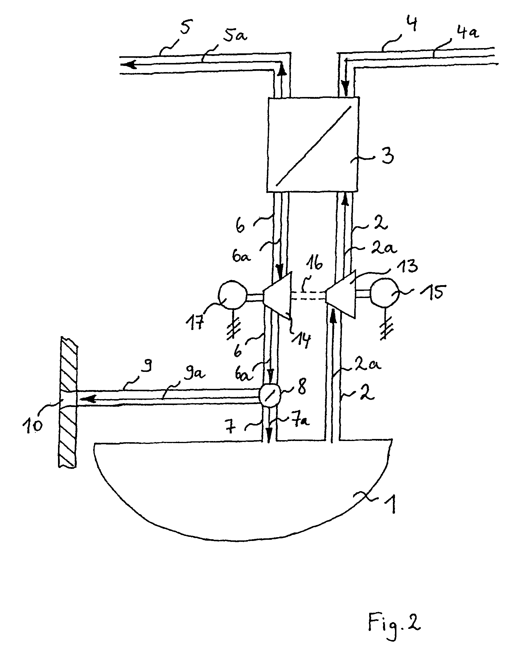
[0021]FIG. 1 shows a schematic representation of a first arrangement for utilizing the heat of waste air for heating the bilge area of aircraft. In FIG. 1, the bilge area is identified by the reference numeral 1 and connected to a heat transfer unit 3 via a first air supply pipe 2. A bilge air flow 2a is drawn in from the bilge area 1 and flows into the heat transfer unit 3 via the first air supply pipe 2. The drawn-in bilge air flow 2a is heated in the heat transfer unit 3 by a waste air heat flow 4a to be cooled. The waste air heat flow 4a to be cooled may consist, for example, of recirculated cabin air, lavatory waste air, galley waste air, waste air from the cooling of electric consumers or the hot air flow of the air-conditioning system of the aircraft. This means that any heat flow created in the aircraft can be effectively utilized for heating the drawn-in bilge air flow 2a. The heating of the drawn-in bilge air flow 2a in the heat transfer unit 3 is either realized directly ...


PUM


Abstract

The present application describes an arrangement and a method for utilizing the heat of waste air for heating the bilge area of aircraft, wherein the bilge area is connected to a heat transfer unit via a first air supply pipe, through which a bilge air flow drawn in from the bilge area flows into the heat transfer unit, wherein the heat transfer unit comprises a second air supply pipe, through which a waste air heat flow to be cooled that is created at another location in the aircraft flows into the heat transfer unit in order to heat the drawn-in bilge air flow, wherein the heat transfer unit comprises a first air discharge pipe, through which the cooled waste air heat flow is discharged, and a second air discharge pipe with a bilge inlet section, and wherein at least a portion of the heated bilge flow is returned to the bilge area via the air discharge pipe and the bilge inlet section.

Description

REFERENCE TO RELATED APPLICATIONS[0001]This application claims the benefit of the filing date of German Patent Application DE 10 2004 061 372 filed Dec. 21, 2004, which disclosure is hereby incorporated by reference.FIELD OF THE INVENTION[0002]The present invention relates to an arrangement and a method for utilizing heat of waste air for heating a bilge area of aircraft.TECHNOLOGICAL BACKGROUND[0003]Due to its location and geometry, the bilge area of aircraft serves as the destination for waste air with higher levels of, for example, waste heat, aromatics or smoke and as a collecting tank for accumulating liquids. For example, the waste water from drains, oil, grease, cleaning agents and condensate forming on the structure or in the insulating materials during temperature changes are accumulated in the bilge area. In order to prevent corrosion, the bilge area is only thermally insulated to a limited degree.[0004]This means that a correspondingly higher expenditure is required for t...

Claims


Application Information

Patent Timeline
Patent Type & Authority Patents(United States)
IPC IPC(8): B64D13/00B60H1/00B64D11/00
CPCB64D13/06B64D2013/0648Y02T50/56Y02T50/50
Inventor MARKWART, MICHAELSCHERER, THOMASSCHAUMANN, OLIVER
Owner AIRBUS OPERATIONS GMBH
Why Eureka
Try Eureka