Image sensing apparatus driving method, image sensing apparatus, and image sensing system

a technology of image sensing apparatus and driving method, which is applied in the direction of color television details, television system, picture signal generator, etc., can solve the problems of insufficient compression of images and insufficient improvement of frame rate, so as to reduce false color generation and sufficient frame rate

Inactive Publication Date: 2011-07-19
CANON KK
View PDF39 Cites 61 Cited by
  • Summary
  • Abstract
  • Description
  • Claims
  • Application Information

AI Technical Summary

Benefits of technology

[0009]The present invention provides an image sensing apparatus driving method, image sensing apparatus, and image capturing system capable of reducing false color generation and obtaining a sufficient frame rate even when the number of pixels increases.
[0015]According to the present invention, it is possible to reduce false color generation and obtain a sufficient frame rate even when the number of pixels increases.

Problems solved by technology

This may make it impossible to sufficiently compress an image.
It may therefore be impossible to sufficiently improve the frame rate when the number of pixels increases.

Method used


Image

  • Image sensing apparatus driving method, image sensing apparatus, and image sensing system
  • Image sensing apparatus driving method, image sensing apparatus, and image sensing system
  • Image sensing apparatus driving method, image sensing apparatus, and image sensing system

Examples


first embodiment

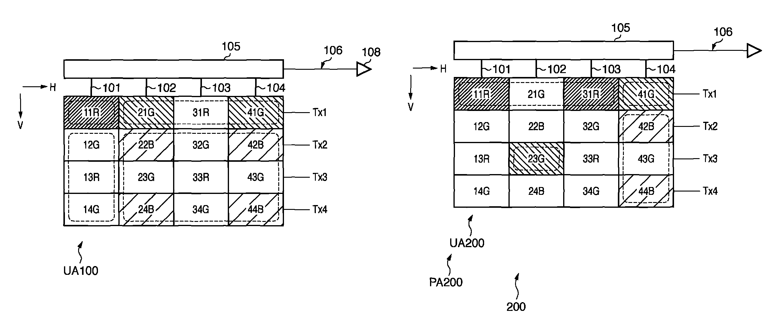
[0112]The image sensing apparatus 200 has the same basic arrangement as in the first embodiment except the arrangement of an image sensing region PA200.

[0113]A unit array UA200 in the image sensing region PA200 includes two fifth photoelectric conversion units 11R and 31R, two sixth photoelectric conversion units 42B and 44B, a seventh photoelectric conversion unit 23G, and an eighth photoelectric conversion unit 41G, as shown in FIG. 5. One (11R) of R pixels (11R, 31R) and one (44B) of B pixels (42B, 44B) are arranged on the first diagonal line of the unit array, and G pixel (41G) and G pixel (23G) are arranged on the second diagonal line of the unit array.

[0114]Unlike the first embodiment, both the seventh photoelectric conversion unit 23G and the eighth photoelectric conversion unit 41G correspond to single G pixel signals. More specifically, the two G pixels have good symmetry after addition or averaging for the unit array UA200. This reduces the shift between the two G pixels a...

fourth embodiment

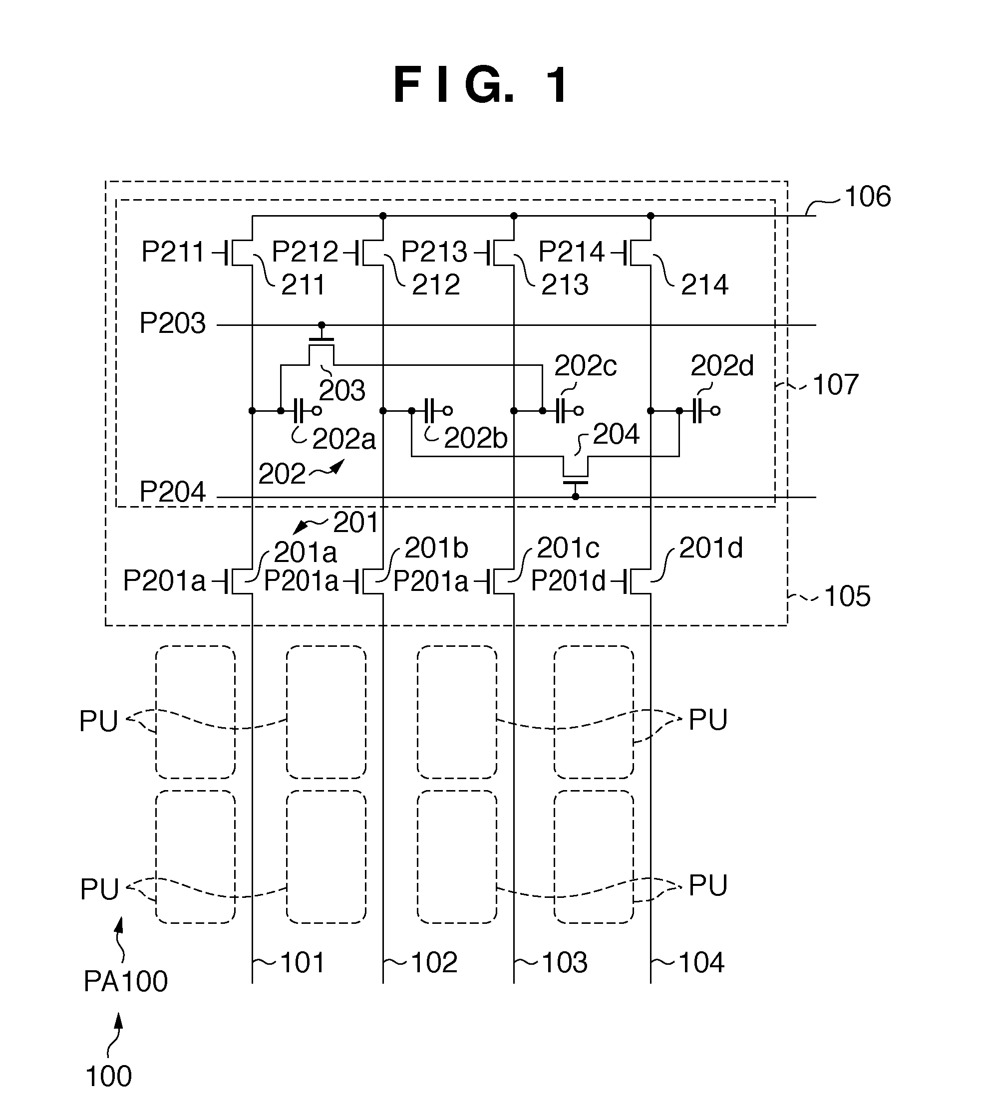
[0146]In the fourth embodiment, however, the signal of the pixel 41G is read out to the upper side via the column signal line 404, and the added signal of the pixels 42B and 44B is read out to the lower side. That is, the number of signals (number of colors) handled by the upper readout circuit can be equal to that of the lower readout circuit.

[0147]In a switch group 201, the switches 201a, 201c, and 201d and the switches 201b and 201d1 individually operate. In readout operation of this embodiment, first, the signal of V=1 (1st row) is transferred to the storage capacitors 202a, 202c, and 202d on the upper side via the switches 201a, 201c, and 201d. Next, the signal of V=3 (3rd row) is transferred to the storage capacitor 202b on the lower side via the switch 201b connected to the column signal line 102. The signals of V=2 (2nd row) and 4 (4th row) are added on the carrier holding unit 1209 and then transferred to the storage capacitor 202d1 on the lower side via the switch 201d1 co...


PUM


Abstract

Since pixel signals are not only added in the row direction but also averaged in the column direction, it is possible to sufficiently increase the frame rate even when the number of pixels increases. Additionally, since the spatial centers of gravity of the added or averaged signals are arranged at equal intervals in a Bayer array, it is possible to reduce false color (moiré) generation and suppress the decrease in the spatial resolution.

Description

BACKGROUND OF THE INVENTION[0001]1. Field of the Invention[0002]The present invention relates to an image sensing apparatus driving method, image sensing apparatus, and image capturing system.[0003]2. Description of the Related Art[0004]Digital cameras, video cameras, portable phones equipped with cameras are recently starting to use a CMOS image sensing apparatus. The indices of performance of an image sensing apparatus are the number of pixels and the image signal readout rate.[0005]To increase the number of pixels, a method of making a plurality of pixels share an active element in a MOS image sensing apparatus has been proposed. In Japanese Patent Laid-Open No. 2005-198001, four pixels share one floating diffusion and one active element. This reduces the pixel pitch and increases the number of pixels per predetermined area.[0006]On the other hand, to speed up pixel signal readout, the number of output channels is increased in a MOS image sensing apparatus. Alternatively, to spee...

Claims


Application Information

Patent Timeline
Patent Type & Authority Patents(United States)
IPC IPC(8): H04N5/335H04N5/347H04N5/374H04N5/376H04N5/378H04N9/07
CPCH04N23/84H04N25/136
Inventor WATANABE, TAKANORIITANO, TETSUYATAKAHASHI, HIDEKAZU
Owner CANON KK
Why Eureka
Try Eureka