Viewing wide angle images using dynamic tone mapping

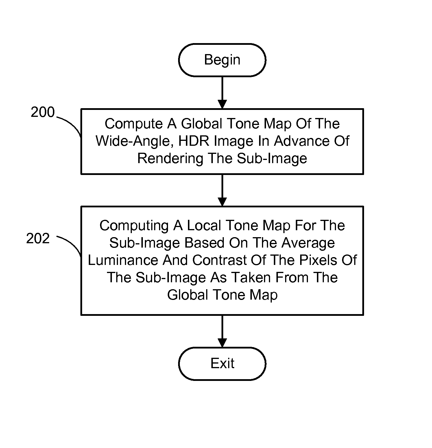
a wide angle image and dynamic tone technology, applied in image enhancement, image analysis, instruments, etc., can solve the problems of global tone mapping creating problems, impractical to pre-compute a local tone map for every possible sub-image, etc., to increase contrast in low contrast areas, smooth out intensity changes

Inactive Publication Date: 2011-07-19
MICROSOFT TECH LICENSING LLC
View PDF13 Cites 49 Cited by
  • Summary
  • Abstract
  • Description
  • Claims
  • Application Information

AI Technical Summary

Benefits of technology

The present dynamic tone mapping technique generally produces a local tone map for a sub-image of a wide-angle, HDR image. This tone map is then used in rendering the sub-image for display. The local tone map creates the brightness and contrast levels that make the details of the sub-image stand out by brightening dark regions and darkening light regions, while increasing the contrast in low contrast areas of the image. In addition, in one embodiment, the present technique can produce the local tone maps for sub-images on the fly so as to make it practical to tone map a sequence of sub-images being generated as part of a pan and zoom session.
In one exemplary embodiment, the present technique generally involves first computing a global tone map of the wide-angle, HDR image in advance of rendering the sub-image. The global tone map is then used during rendering of the sub-image to compute a local tone map based on the average luminance and contrast of the pixels of the sub-image. In addition, when the sub-image being tone mapped is part of a sequence of sub-images being rendered for display during a viewer-executed panning and / or zooming operation, the local tone maps can be kept from changing too rapidly by adding a hysteresis feature to smooth out the intensity changes between sub-images.

Problems solved by technology

Unfortunately, this global tone mapping creates problems when zooming in on a wide angle image.
However, it is impractical to pre-compute a local tone map for every possible sub-image that might be displayed.

Method used


Image

  • Viewing wide angle images using dynamic tone mapping
  • Viewing wide angle images using dynamic tone mapping
  • Viewing wide angle images using dynamic tone mapping

Examples


Embodiment Construction

In the following description of embodiments of the present invention reference is made to the accompanying drawings which form a part hereof, and in which are shown, by way of illustration, specific embodiments in which the invention may be practiced. It is understood that other embodiments may be utilized and structural changes may be made without departing from the scope of the present invention.

1.0 The Computing Environment

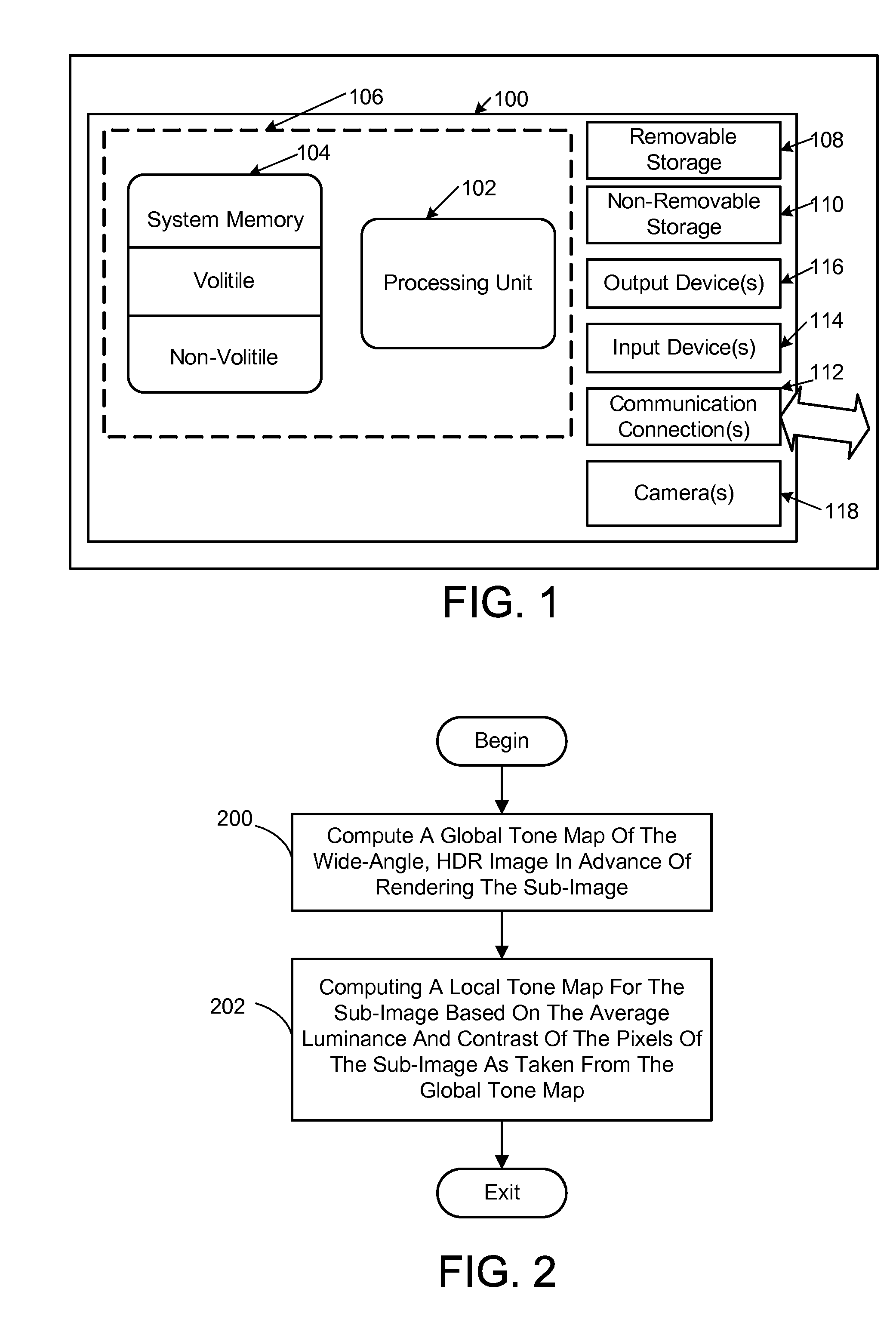
Before providing a description of embodiments of the present dynamic tone mapping technique, a brief, general description of a suitable computing environment in which portions thereof may be implemented will be described. The present technique is operational with numerous general purpose or special purpose computing system environments or configurations. Examples of well known computing systems, environments, and / or configurations that may be suitable include, but are not limited to, personal computers, server computers, hand-held or laptop devices, multiproces...


PUM


Abstract

A dynamic tone mapping technique is presented that produces a local tone map for a sub-image of a wide-angle, high dynamic range (HDR), which is used in rendering the sub-image for display. The technique generally involves first computing a global tone map of the wide-angle, HDR image in advance of rendering the sub-image. The global tone map is then used during rendering to compute a local tone map based on the average luminance and contrast of the pixels of the sub-image. In addition, the sub-image can be tone mapped as part of the rendering of a sequence of sub-images during a viewer-executed panning and / or zooming session. In this case, the local tone maps can be kept from changing too rapidly by adding a hysteresis feature to smooth out the intensity changes between successive sub-images.

Description

BACKGROUNDA normal image is typically captured with a camera having a 30-70 degree field of view. Special cameras and lenses can produce much wider fields of view, and by using software multiple images can be stitched together into even wider fields of view all the way to a complete sphere. In addition, such images can be generated using a virtual camera viewing a virtual 3D world. These wide angle images often are high resolution and are created with a high dynamic range (HDR).When viewing the foregoing wide angle images one often wants to be able to pan and zoom to examine a smaller portion of the image to appreciate the details. However, in order to display a sub-image of a wide angle, HDR image on a typical display device, tone mapping is needed. Tone mapping maps the tonal values of the HDR image to the limited dynamic range available on the display device. Typically, the whole image is “tone mapped” in advance of display so that much of the scene appears as natural as possible...

Claims


Application Information

Patent Timeline
Patent Type & Authority Patents(United States)
IPC IPC(8): G06K9/40
CPCG06T5/007G06T5/40G06T2207/20208
Inventor COHEN, MICHAELUYTTENDAELE, MATTHEWKOPF, JOHANNES
Owner MICROSOFT TECH LICENSING LLC
Why Eureka
Try Eureka