
Mammography system and method employing offset compression paddles, automatic collimation, and retractable anti-scatter grid

a compression paddle and offset technology, applied in the field of mammography, can solve the problems of affecting the patient's comfort and ability, affecting the patient's ability to perform normal use, and being heavy and somewhat thicker, so as to improve the patient's ability, improve the image quality, and improve the effect of ability

Inactive Publication Date: 2011-07-26
HOLOGIC INC
View PDF20 Cites 34 Cited by
  • Summary
  • Abstract
  • Description
  • Claims
  • Application Information

AI Technical Summary

Benefits of technology

[0008]Another object is to employ compression paddles that match both the size and position of the patient's breast relative to the proximal edge of a digital x-ray image receptor so as to improve image quality, patient comfort and the ability of the health professional to position the breast optimally for imaging.

Problems solved by technology

Such matching is desirable because the use of a small size paddle on a large breast can result in uneven and inadequate breast compression and may not allow full-breast imaging, while using a large paddle on a small breast can impede access to the breast, which is important during the compression cycle in order to optimize the amount of breast tissue brought into the field of view of the image receptor.
They have many advantages, but also tend to be heavier and somewhat thicker.
Typically, they are not designed to be removable in normal use. so a system normally will employ only one size image receptor.
These characteristics can presents challenges for some imaging procedures and breast sizes, particularly for the mediolateral oblique view (MLO) taken as a part of typical breast x-ray imaging.
In some views, such as the MLO view, and particularly for smaller breasts, this may present some difficulty as the cassette may have to be pressed against the armpit in order to approximately center the breast relative to the proximal edge of the film (the edge closest to and parallel to the chest wall).
Thus, centering the breast can be difficult or impossible in some cases, particularly for the MLO view and patients with smaller breasts, with the result that optimal positioning of the breast may not be possible for some views and patients.
To applicants' knowledge, these and other issues regarding compression paddle use with fiat panel digital receptors in mammography have not been solved and perhaps have not been even addressed.

Method used


Image

  • Mammography system and method employing offset compression paddles, automatic collimation, and retractable anti-scatter grid
  • Mammography system and method employing offset compression paddles, automatic collimation, and retractable anti-scatter grid
  • Mammography system and method employing offset compression paddles, automatic collimation, and retractable anti-scatter grid

Examples


Embodiment Construction

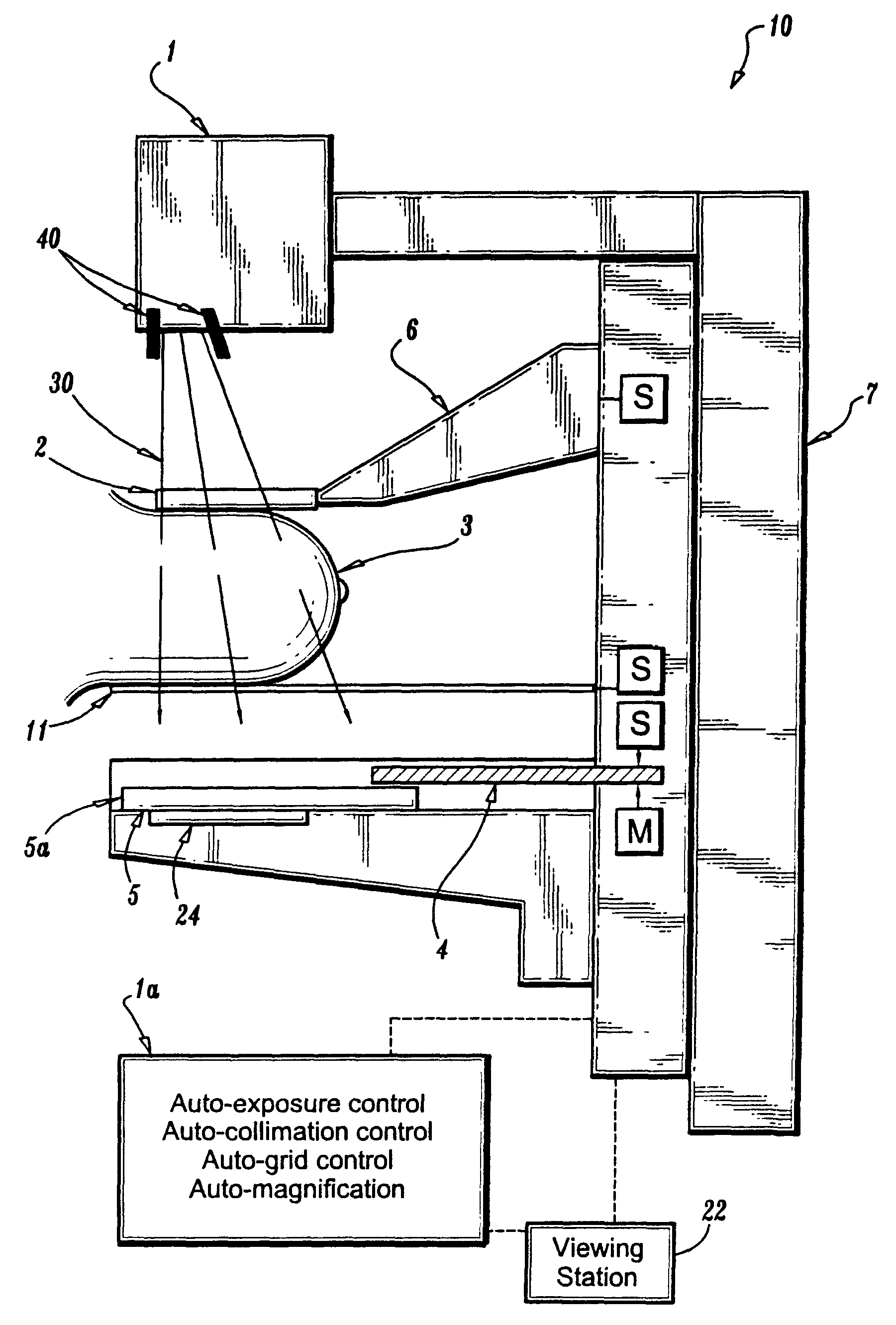
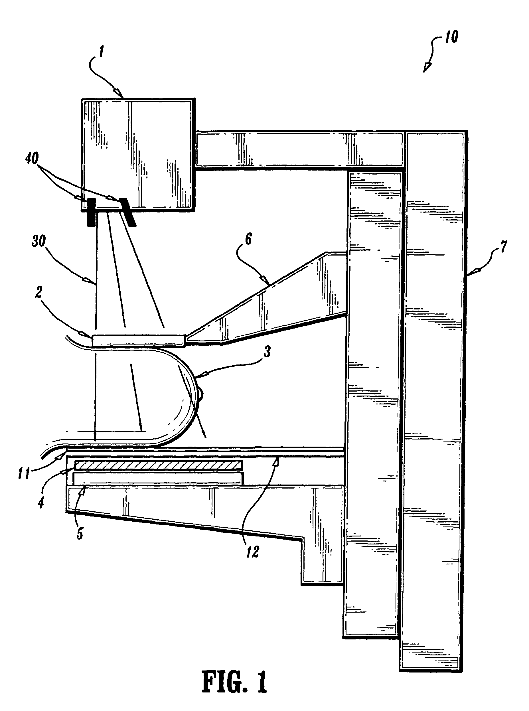
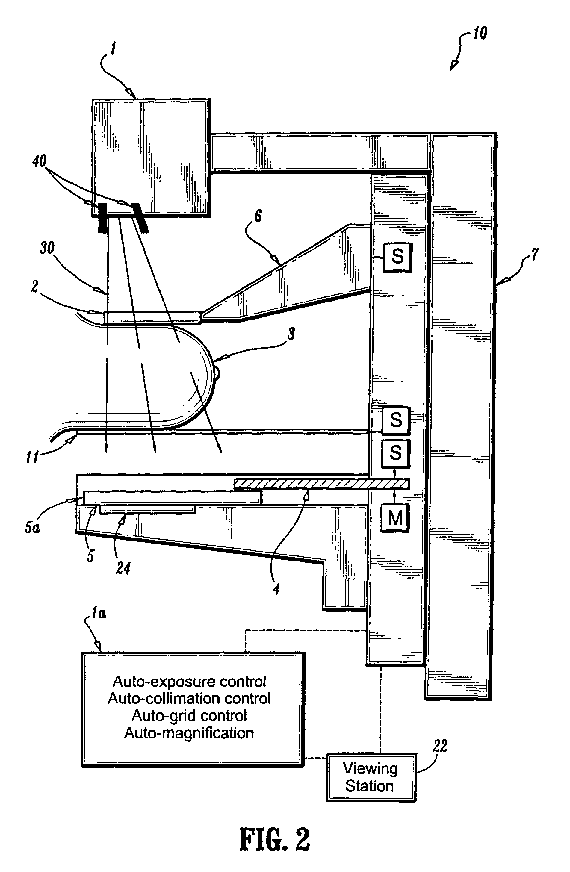
[0019]Referring to FIG. 1, an x-ray source 1 is at one end of a generally C-shaped frame 7 and a flat panel digital x-ray imaging receptor 5 is at the other end. X-ray source 1 includes a collimator schematically illustrated at 40 to confine an x-ray beam 30 emitted from source 1 to a desired footprint at receptor 5, typically no larger than the area of receptor 5 and preferably just enough to image a patient's breast 3 or at least a selected part thereof, as compressed toward receptor 5 by a compression paddle 2 mounted on an arm 6 that in turn mounts to frame 7. A lower platform 11, often called a breast tray, is immediately below the breast, and a scatter-reducing grid 4 is between breast tray 11 and x-ray receptor 5 and is housed in the same enclosure 12 with the receptor. As is known in the art, frame 7 can rotate between horizontal and vertical directions of x-ray beam 30.

[0020]In use for a CC view, paddle 2 and its supporting arm 6 are moved up , breast 3 is positioned on tra...


PUM


Abstract

A mammographic imaging system is optimized for use with a single fixed size flat panel digital image receptor. It accommodates compression devices (paddles) of varying sizes, and positions them properly in the field of view of the image receptor. When a compression paddle with size smaller than the field of view of the image receptor is used, the compression paddle can be shifted laterally in the direction parallel to the chest wall, so as to facilitate different views of different size breasts, and permit the image receptor to image as much of the desired tissue as possible. An automatic x-ray collimator restricts the x-ray illumination of the breast in accordance with compression paddle size and location in the field of view. An anti-scatter grid, mounted inside the image receptor enclosure, just below the top cover of the enclosure, can be retracted out of the field of view of the image receptor for use in magnification imaging.

Description

CROSS-REFERENCE TO RELATED APPLICATIONS[0001]This application is a Rule 1.53(b) Continuation of U.S. Ser. No. 12 / 463,256, filed May 8, 2009 now U.S. Pat. No. 7,688,940, which in turn is a continuation of Ser. No. 12 / 014,405, filed Jan. 15, 2008, now U.S. Pat. No. 7,609,806, which in turn is a continuation of Ser. No. 11 / 607,748, filed Nov. 30, 2006, now U.S. Pat. No. 7,319,735, which in turn is a continuation of Ser. No. 10 / 496,049, filed Oct. 18, 2004, now U.S. Pat. No. 7,443,949, which is a Section 371 national stage of international application no. PCT / US02 / 33058 filed Oct. 17, 2002, claiming the benefit of U.S. Provisional Application Ser. No. 60 / 350,213 filed Oct. 19, 2001, the entire contents of each of which are incorporated herein by reference.FIELD[0002]This patent specification is in the field of mammography and specifically mammography employing flat panel, digital x-ray receptors rather than x-ray film.BACKGROUND[0003]X-ray mammography machines typically use an x-ray sou...

Claims


Application Information

Patent Timeline
IPC IPC(8): A61B6/04
CPCA61B6/0414A61B6/06A61B6/04A61B6/502A61B6/4233A61B6/4291A61N5/1069
Inventor DEFREITAS, KENNETH F.PELLEGRINO, ANTHONYFARBIZIO, THOMAS A.JANER, ROMANHITZKE, GEORGIA
Owner HOLOGIC INC
Learn More