Air conditioner

a technology for air conditioners and heat exchangers, applied in the field of air conditioners, can solve the problems of only falling room temperature and rising indoor relative humidity, increasing temperature in indoor heat exchangers, and giving users unpleasant feelings, etc., and achieve the effect of reducing the change of temperature more greatly

Inactive Publication Date: 2011-08-02
FUJITSU GENERAL LTD
View PDF22 Cites 22 Cited by
  • Summary
  • Abstract
  • Description
  • Claims
  • Application Information

AI Technical Summary

Benefits of technology

[0008]Accordingly, an object of this invention is to raise the temperature of discharged air by opening / closing the damper at appropriate timings and enhance the capability of dehumidification during a cooling / defumidifying operation, to prevent an indoor environment from being deteriorated particularly when the damper is broken down in enhancing the capability of dehumidification and to prevent condensation in an indoor blower due to introduced air (raw gas) in enhancing the capability of dehumidification during a cooling / defumidifying operation, thereby to improve the degree of comfort.

Problems solved by technology

Meanwhile, during this cooling / dehumidification operation, if the temperature of the indoor heat exchanger has not reached a dew point temperature, the room temperature only falls and the indoor relative humidity rises.
So, an unpleasant feeling may be given to users.
However, with an increase in the quantity of wind, the temperature in the indoor heat exchanger rises and the capability of dehumidification is sacrificed.

Method used


Image

  • Air conditioner
  • Air conditioner
  • Air conditioner

Examples


Embodiment Construction

[0167]Now, referring to FIGS. 1 to 8, an explanation will be given of a basic embodiment of this invention.

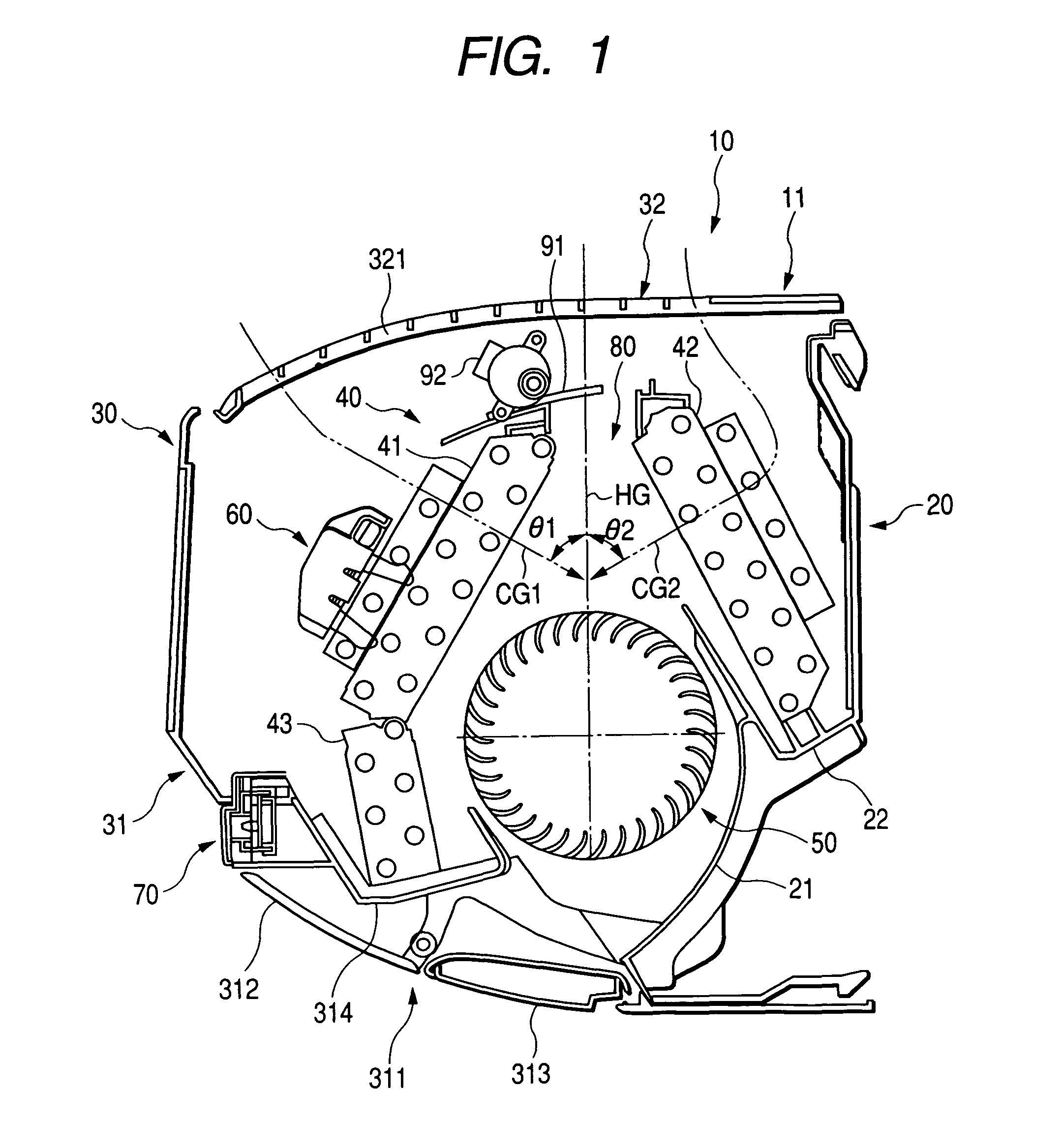
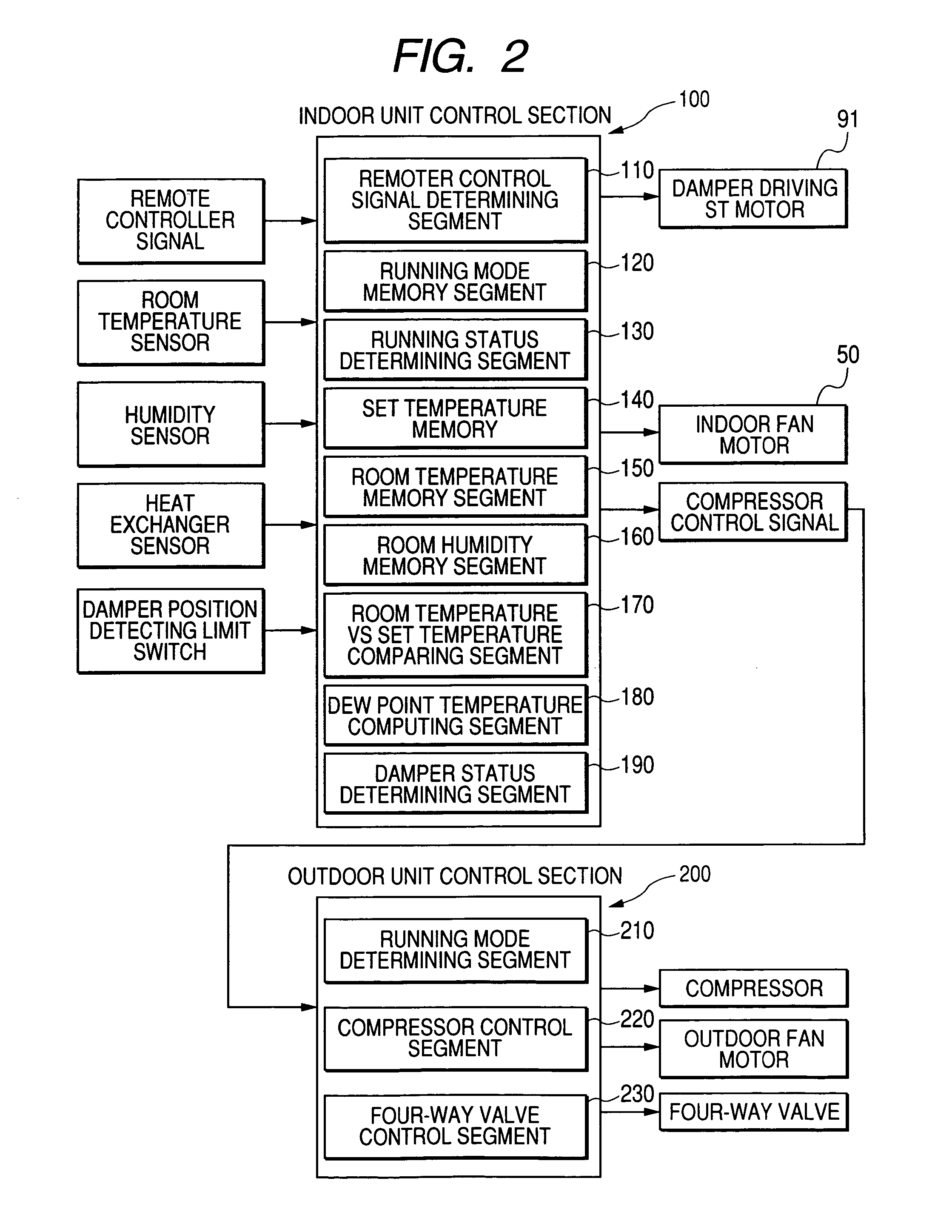
[0168]FIG. 1 is a sectional view of an internal structure of an indoor unit of an air conditioner according to this invention. FIG. 2 is a block diagram of a control system according to this invention. FIGS. 3 and 4 are a flowchart of a first exemplary control operation according to this invention and a view for explaining a temperature control band, respectively. FIGS. 5 and 6 are a flowchart of a second exemplary control operation according to this invention and a view for explaining a humidity control band, respectively. FIGS. 7 and 8 are a flowchart of a third exemplary control operation according to this invention and a view for explaining a dew point temperature control band, respectively.

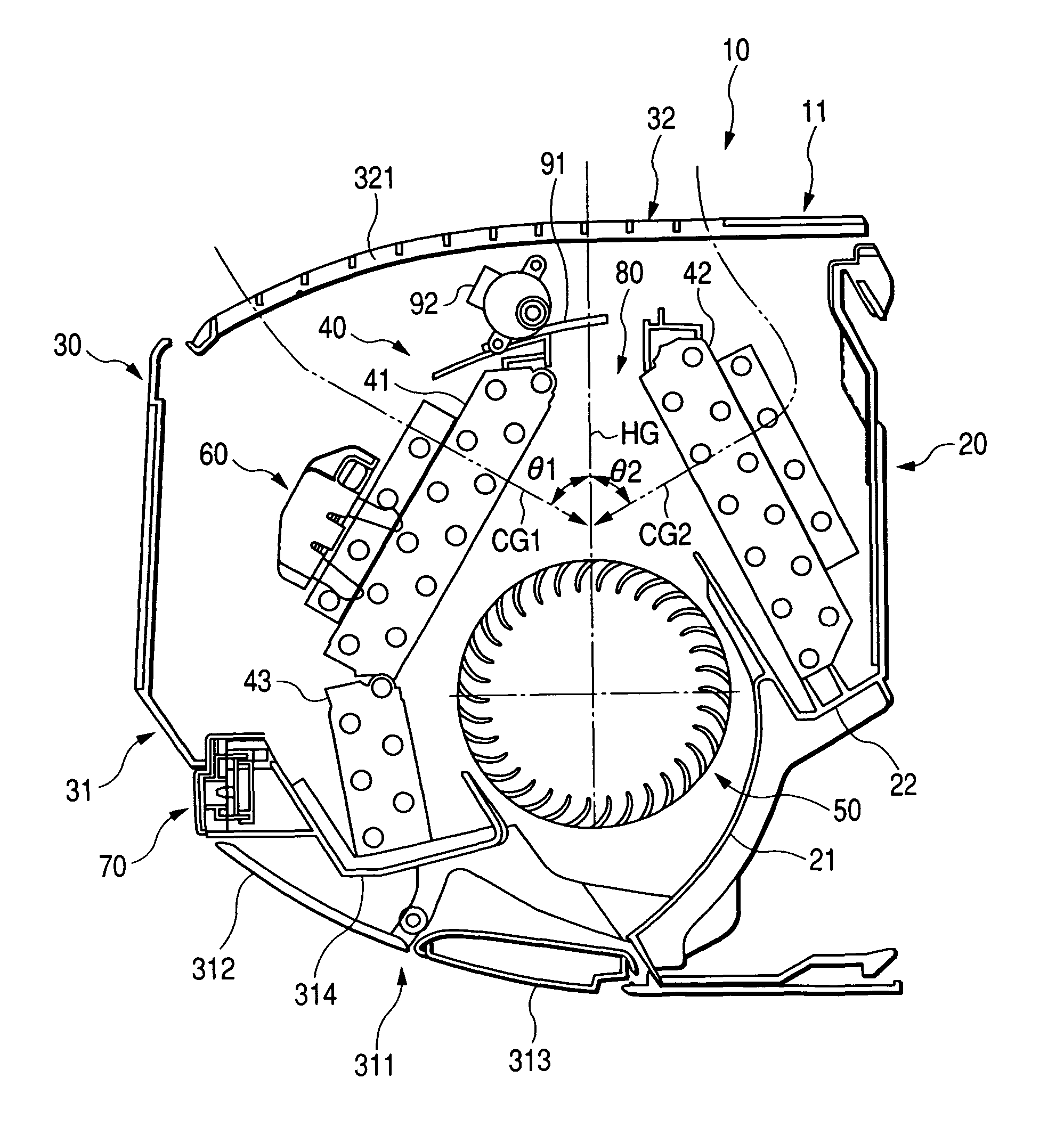
[0169]The air conditioner according to this invention includes an indoor unit 10 as seen from FIG. 1. In this embodiment, the indoor unit 10 has a wall-mounted housing (enclosure) 11 inc...


PUM


Abstract

Between two heat exchangers of a first heat exchanger unit 41 and a second heat exchanger unit 42 included in an indoor heat exchanger 40, an opening 80 is arranged for introducing indoor air sucked from an air inlet 321 into an indoor blower 50 without being heat-exchanged. At the opening 80, a damper 91 is arranged for adjusting the opening rate of the opening 80, which is driven by a predetermined driving member 92. During a cooling cycle running of a freezing cycle, the opening rate of the opening 80 and / or the devices included in the freezing cycle such as a compressor, blower and expansion valve are controlled alone or in combination so that the temperature of the indoor heat exchanger 40 is lower than a dew point temperature of the indoor air.

Description

BACKGROUND OF THE INVENTION[0001]This invention relates to an air conditioner, and more specifically to a technique for changing a ratio between latent heat and sensible heat in an indoor heat exchanger during running of a cooling cycle, thereby improving capability of dehumidification (latent heat).[0002]An air conditioner in a cooling / heating system has a freezing cycle including a compressor, a four-way valve, an outdoor heat exchanger, an expansion valve and an indoor heat exchanger. During a heating operation, the air conditioner circulates coolant in the course of the compressor→four-way valve→indoor heat exchanger→expansion valve→outdoor heat exchanger→four-way valve→compressor and employs the indoor heat exchanger as a condenser and the outdoor heat exchanger as an evaporator.[0003]On the other hand, during a cooling operation inclusive of dehumidification, the air conditioner circulates the coolant in the course of compressor→four-way valve→outdoor heat exchanger→expansion ...

Claims


Application Information

Patent Timeline
Patent Type & Authority Patents(United States)
IPC IPC(8): F25D17/04F25D17/00F24F3/14F24F1/0057F24F1/0063F24F1/0067F24F1/0071F24F1/0083F24F11/76
CPCF24F1/0007F24F1/0059F24F3/1405F24F11/0012F24F11/0015F24F11/0079F24F13/12F24F2001/0048Y02B30/746F24F11/30F24F2110/10F24F2110/20F24F11/77F24F1/0057Y02B30/70F24F1/0067F24F13/22F24F1/0063F24F1/0071F24F1/0083F24F11/52F24F11/84F24F11/76F24F11/86F24F11/38F24F11/56
Inventor HAMADA, MAMORUIGARASHI, HIROKIITAGAKI, ATSUSHIARIMA, TAKAFUMIWATANUKI, HIROAKISASAKI, YOSHIHIROUSUI, MASAMITSU
Owner FUJITSU GENERAL LTD
Why Eureka
Try Eureka