Dual dispensing container

a container and dual technology, applied in the field of containers, can solve the problems of damage and deformation of corners, defined between the front, back and side panels, and achieve the effects of improving the configuration of perforations or slits, and improving the perforation of tear lines

Active Publication Date: 2011-08-02
KELLOGG CO
View PDF31 Cites 72 Cited by
  • Summary
  • Abstract
  • Description
  • Claims
  • Application Information

AI Technical Summary

Benefits of technology

[0010]An advantage of the present invention is to provide a container which can be used for dual dispensing of a product contained therein at a user's preference.
[0011]Another advantage of the present invention is to provide a container with improved perforation of a tear line which allows smooth tearing of the tear line from the carton without tearing corners defined between the panels.
[0012]Still another advantage of the present invention is to provide an improved configuration of the perforations or slits along the tear line, which prevents the corners defined between the front, back, and side panels, from being damaged and deformed and provides for smooth tearing of the tear line from the carton.

Problems solved by technology

One of the most common problems associated with the prior art patents is a configuration of the perforations or slits along the tear line, which results in the corners, defined between the front, back, and side panels, being damaged and deformed.

Method used


Image

  • Dual dispensing container
  • Dual dispensing container
  • Dual dispensing container

Examples


Embodiment Construction

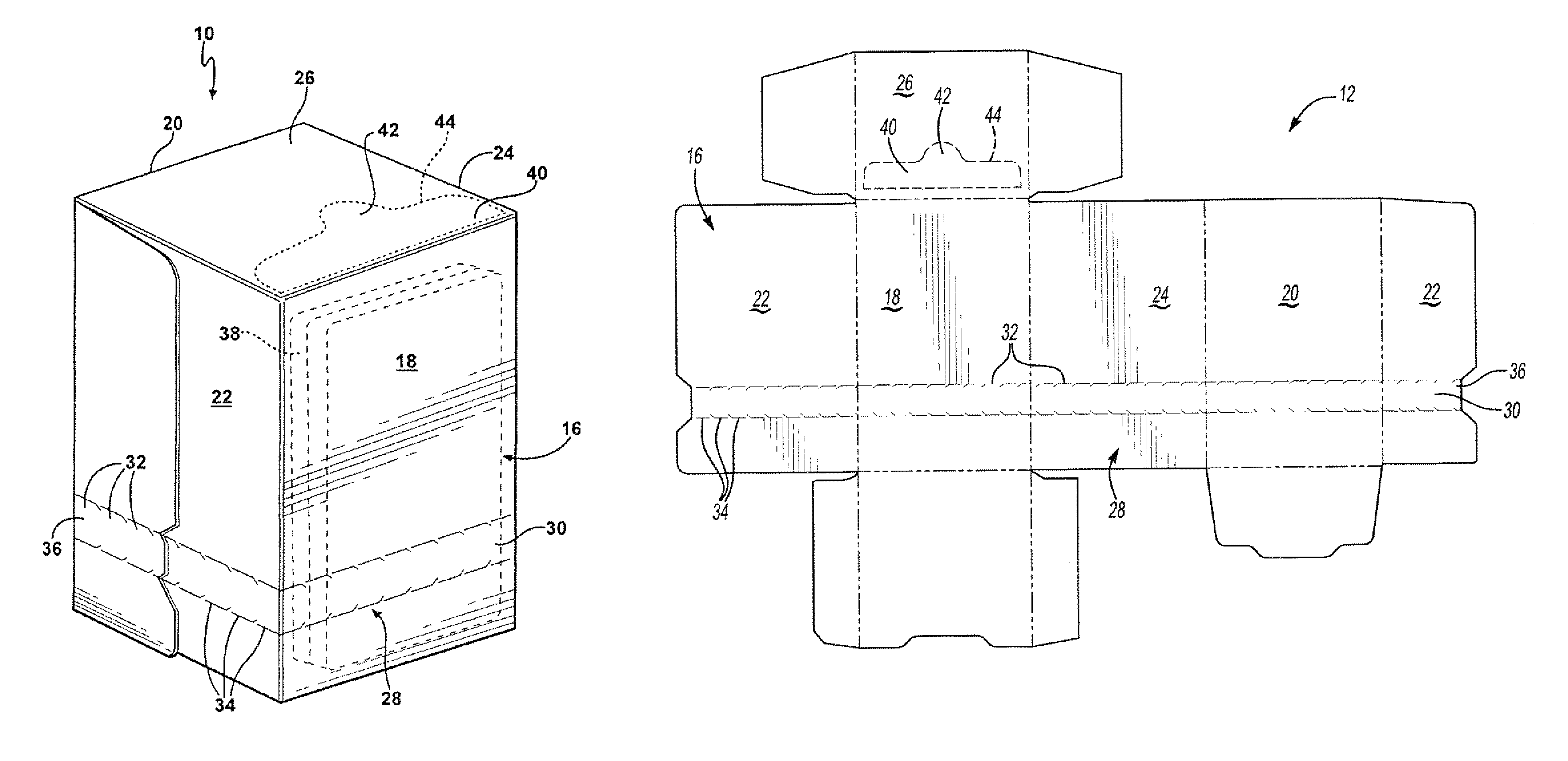
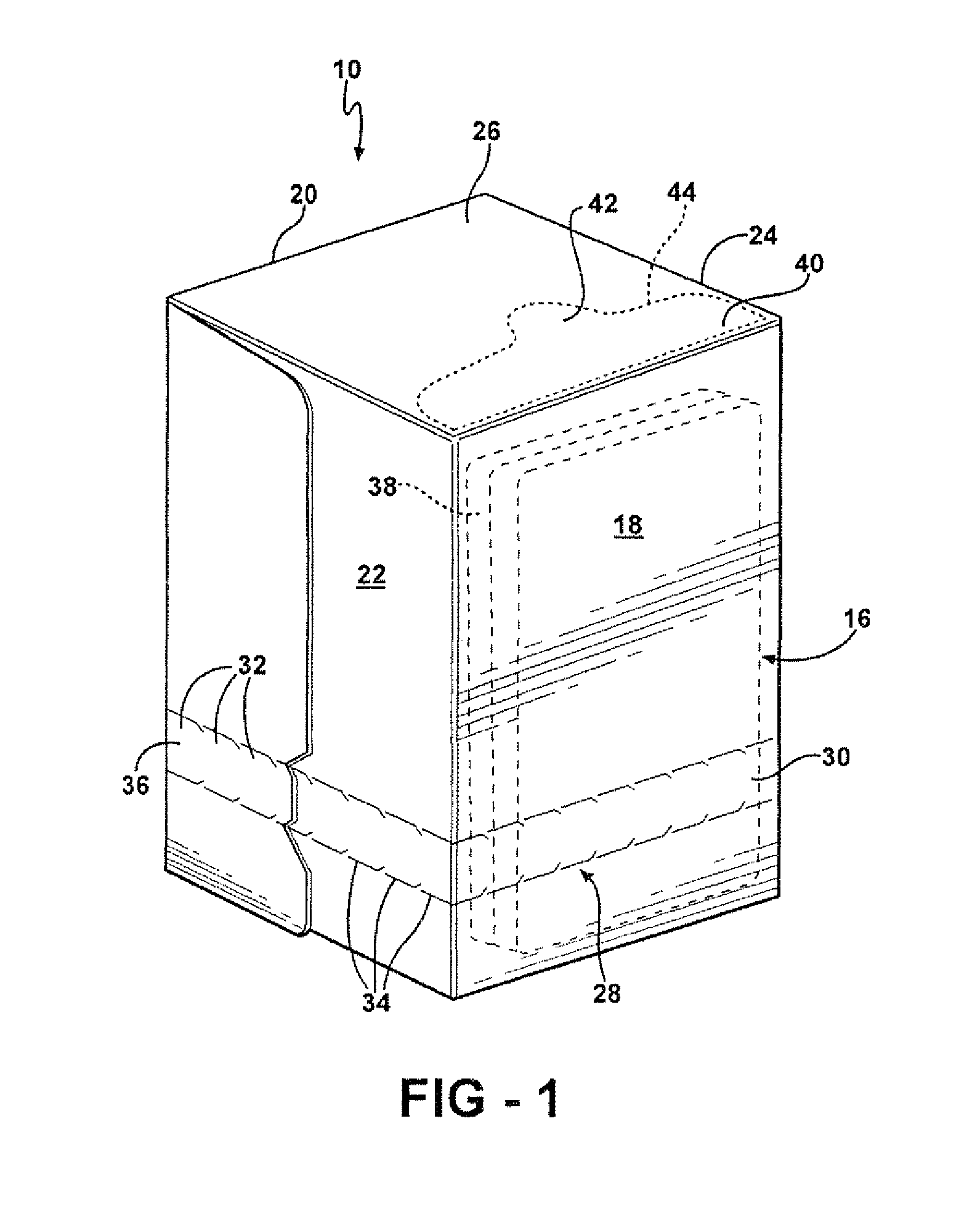
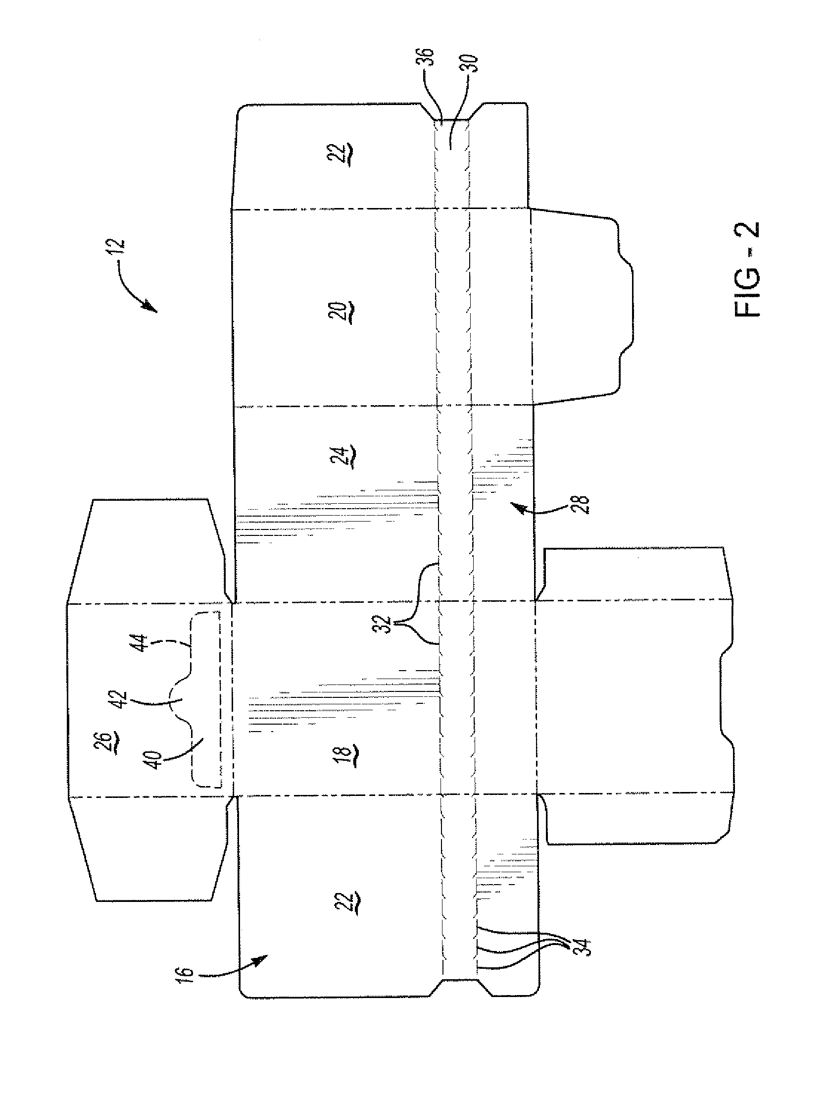
[0020]Referring to the FIGS. 1 and 2, wherein like numerals indicate like or corresponding parts throughout the several views, a container is generally shown at 10. The container 10 is formed from a blank of material, such as for example corrugated material, plastic or paperboard, generally shown at 12 in FIG. 2. The blank 12 includes an inner surface (not shown) and an outer surface, generally indicated at 16 and adapted for receiving printed material. The blank 12 is divided into four parts, such as, for example, a front panel 18, a back panel 20, and side panels 22, 24, with one of the side panels 22 being formed from two halves connected to one another by glue or other mechanical means known to those skilled in the art. In the illustrated embodiment, the front panel 18, the back panel 20, and the side panels 22 and 24 have equal heights and widths but other heights and widths would be obvious to those of ordinary skill in the art.

[0021]The container 10 includes a tear line or te...


PUM


Abstract

A container of the present invention is designed for shipping and holding various items. The container is formed from a blank of a material, such as corrugated material, plastic, paperboard, etc. and includes side panels extending between a top portion and a bottom portion. A tear line extends around the side panels for disengaging the top portion from the container thereby exposing all of the items extending along the side panels. An improved configuration of the perforations or slits along the tear line prevents the corners defined between the side panels from being damaged and deformed and provides for smooth tearing of the tear line from the container. A second tear section is defined in the a portion of the container by a perforation line with the tear section being separable from the top portion thereby partially exposing the items contained in the container.

Description

BACKGROUND OF THE INVENTION[0001]1. Field of the Invention[0002]The subject invention relates to containers, such as for example corrugated containers, paperboard containers, etc. having tear lines and blanks for making such containers. It should be understood by those of ordinary skill in the art that the word container is being used broadly to include, but not be limited to boxes, cartons, bags etc. and not limited in anyway to the material used.[0003]2. Description of the Prior Art[0004]Today, many types of containers have been developed for the attractive packaging of articles, such as food products, drug items, cosmetics, and the like. Conventionally, the containers are formed from a one-piece blank of material which is cut, scored and folded to produce a generally rectangularly shaped box.[0005]The art is replete with various other designs of cartons, which are disclosed in U.S. Pat. Nos. D436,859 to Botsford et al.; 5,881,884 to Podosek; 5,979,749 to Bozich; 6,073,833 to Desr...

Claims


Application Information

Patent Timeline
Patent Type & Authority Patents(United States)
IPC IPC(8): B65D17/28
CPCB65D5/541B65D5/5445B65D5/542
Inventor PEZZOLI, PAUL
Owner KELLOGG CO
Why Eureka
Try Eureka