Organic electroluminescent device and production method of the device, and display apparatus

a production method and electroluminescent device technology, applied in the direction of organic semiconductor devices, discharge tube luminescnet screens, natural mineral layered products, etc., can solve the problems of insufficient use for further improvement of the characteristics of the device, insufficient lifetime, and inability to provide sufficient emission intensity of the device, etc., to achieve the effect of long lifetime and high efficiency

Inactive Publication Date: 2011-08-02
CANON KK
View PDF9 Cites 143 Cited by
  • Summary
  • Abstract
  • Description
  • Claims
  • Application Information

AI Technical Summary

Benefits of technology

[0020]The present invention has been accomplished in view of the above problems, and it is, therefore, an object of the present invention to provide an organic electroluminescent device having high efficiency and a long lifetime, and a production method of the device.
[0022]According to the present invention, there can be provided an organic electroluminescent device having high efficiency and a long lifetime, and a production method of the device.

Problems solved by technology

However, the coating organic electroluminescent device involves the two problems to be solved that the device cannot provide sufficiently large emission intensity and does not have a sufficient lifetime.
However, the use is insufficient for further improvement in the characteristics of the device because the use simultaneously involves the problems of generation of an interface barrier between the hole injection layer and another layer and an increase in resistance of the hole injection layer itself.
However, because the technology involves joining of organic compounds soluble in a non-polar solvent, it is difficult to apply the technology disclosed in the document to a coating organic electroluminescent device.

Method used


Image

  • Organic electroluminescent device and production method of the device, and display apparatus
  • Organic electroluminescent device and production method of the device, and display apparatus
  • Organic electroluminescent device and production method of the device, and display apparatus

Examples


example 1

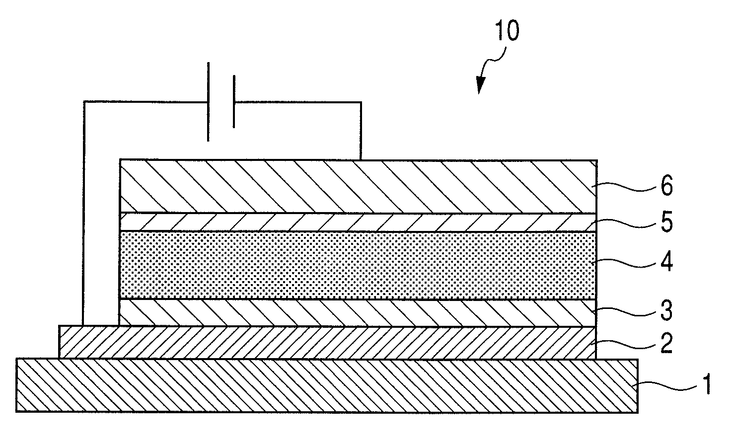
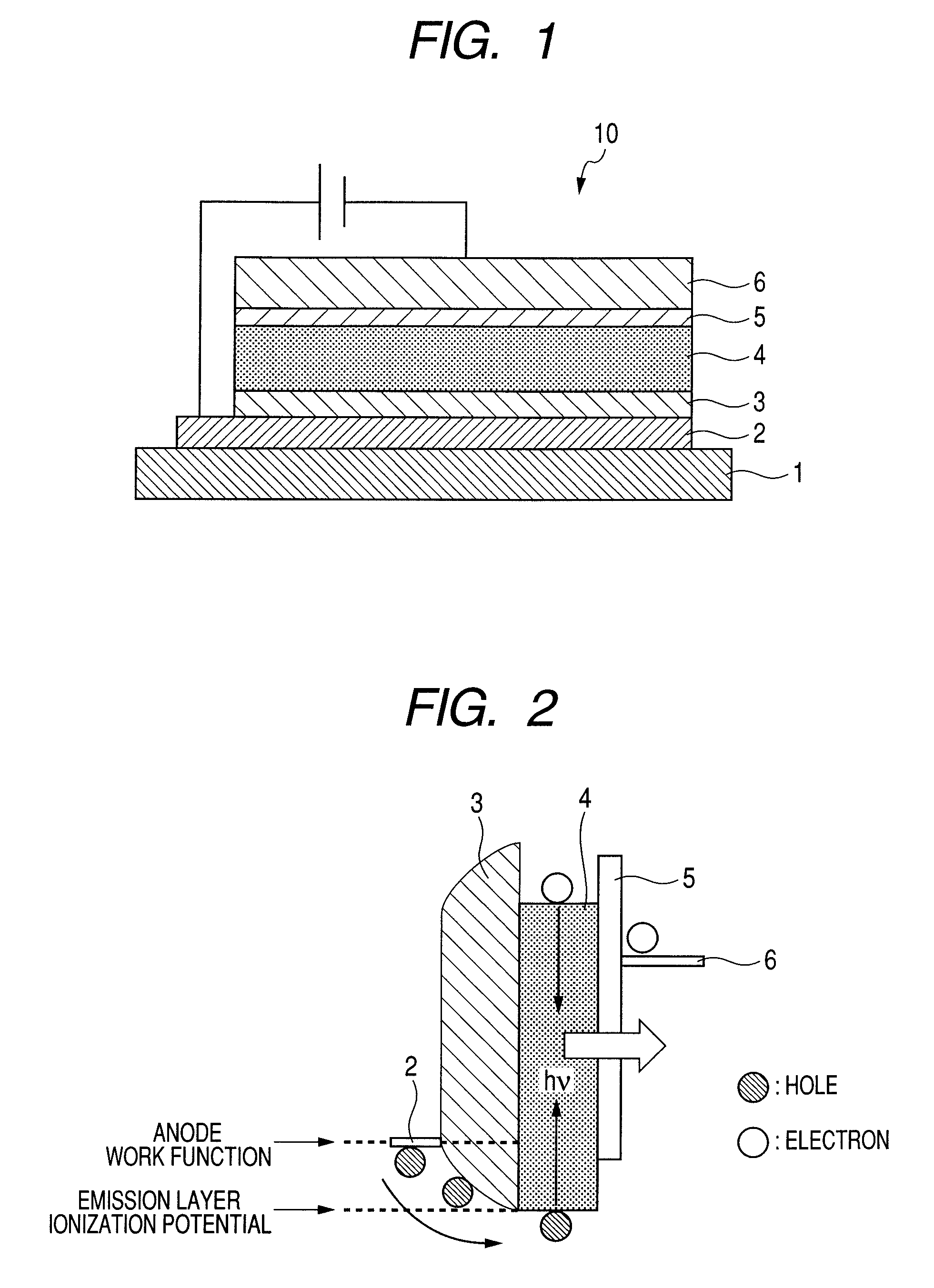
[0082]An organic electroluminescent device having a device structure illustrated in FIG. 1 was produced.

[0083]In the production of the organic electroluminescent device, the following compounds and the like were used as constituent members.[0084]Substrate 1: glass substrate[0085]Anode 2: indium tin oxide (ITO)[0086]Inorganic compound layer 3: MoOx (the oxygen content (x value) being changed continuously)[0087]Organic emission layer 4: oligofluorene compound (host) shown below and Ir(C8-piq)3 (guest) shown below

[0088][0089]Electron injection layer 5: Cs2CO3 [0090]Cathode 6: Al

[0091]Next, a specific production process for the organic electroluminescent device will be described. First, ITO was formed into a film on the glass substrate (substrate 1) by sputtering, whereby the anode 2 was formed. At this time, the anode had a film thickness of 100 nm.

[0092]Next, an MoOx thin film was formed by DC sputtering by use of Mo metal as a target, whereby the inorganic compound layer 3 was formed...

example 2

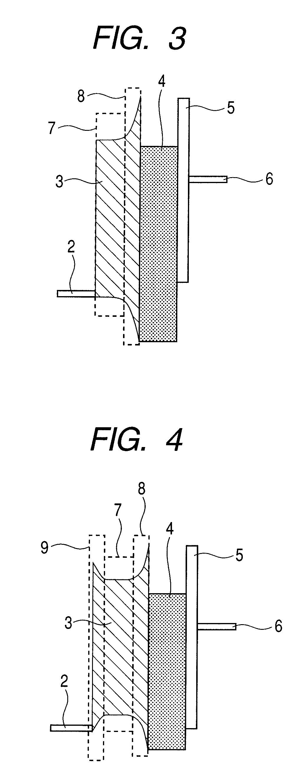
[0096]A device was produced by following the same procedure as in Example 1 with the exception that an electron-blocking layer was further provided between the organic emission layer and the inorganic compound layer by a below-mentioned method.

[0097]In this example, polyvinyl carbazole (PVK) was employed as a constituent material for the electron-blocking layer. In this example, the electron-blocking layer was formed by applying a 1.0-wt % solution of PVK in chlorobenzene by spin coating at 1,000 rpm. At this time, the electron-blocking layer had a film thickness of about 30 nm.

[0098]The resultant device was evaluated in the same manner as in Example 1. As a result, when a DC voltage of 10 V was applied to the device, a current flowed in the device. At this time, the current density was 32 mA / cm2, and the device was observed to emit red light at a luminance of 400 cd / m2.

[0099]Comparing this example with Example 1, the additional provision of the electron-blocking layer (PVK layer) w...


PUM

PropertyMeasurementUnit
ionization potentialaaaaaaaaaa
conductivityaaaaaaaaaa

Abstract

Provided are an organic electroluminescent device having high efficiency and a long lifetime, and a production method of the device. The organic electroluminescent device includes an anode, a cathode, and a stacked body interposed between the anode and the cathode and formed by sequentially stacking at least an inorganic compound layer and an organic emission layer, in which the inorganic compound layer has a hole-transporting ability and a work function of the inorganic compound layer changes continuously in a film thickness direction of the inorganic compound layer.

Description

BACKGROUND OF THE INVENTION[0001]1. Field of the Invention[0002]The present invention relates to an organic electroluminescent device and a production method of the device, and a display apparatus.[0003]2. Description of the Related Art[0004]An electroluminescent device (EL device) has been attracting attention because the device is of a self-emission type, has high visibility, is excellent in display performance, can respond at a high speed, and can achieve a thickness reduction, so that the device has a potential to serve as a display device such as a flat panel display.[0005]Of the electroluminescent device, an organic electroluminescent device using an organic compound as a light-emitting body has, for example, the characteristics that the device can be driven at a lower voltage than the voltage at which an inorganic electroluminescent device is driven, the area of the device can be easily enlarged, and the device can easily provide a desired emission color by selecting an appro...

Claims


Application Information

Patent Timeline
Patent Type & Authority Patents(United States)
IPC IPC(8): H01L51/54
CPCH01L51/5088H01L51/0042H01L2251/5346H10K85/146H10K50/17H10K2101/80
Inventor SHIOYA, SHUNSUKE
Owner CANON KK
Why Eureka
Try Eureka