Method and apparatus for generating a metering pulse

a metering pulse and pulse technology, applied in the field of telecommunications, can solve the problems of undesirable affecting the audio quality of a phone call or other communication, high voltage and current, and noise at much higher frequencies, so as to reduce noise and power consumption, the effect of maximizing and reducing power consumption

Inactive Publication Date: 2011-08-02
SILICON LAB INC
View PDF10 Cites 15 Cited by
  • Summary
  • Abstract
  • Description
  • Claims
  • Application Information

AI Technical Summary

Benefits of technology

[0013]In another aspect, the present invention includes a method including setting a gain value for a DAC structure of a subscriber line interface circuit (SLIC) to a maximum level, generating a metering pulse in the DAC structure using the gain value, and determining whether a ramp portion of the DAC structure reaches a maximized level before the metering pulse reaches a ramp envelope value. The gain value may be adjusted downwardly if the ramp portion does not reach the maximum level. Furthermore, the gain value may be adjusted to a value of less than half of its maximum level so that at least part of the gain portion of the DAC structure can be disabled, reducing power consumption.
[0014]In yet other embodiments, a SLIC may include an audio path to transmit audio signals from the SLIC to a subscriber line and a pulse metering path to generate a metering pulse for transmission via the subscriber line. The pulse metering path may include a metering generator to generate a digital sine wave from a plurality of stored values, a first interpolator to interpolate the digital sine wave, a filter to filter the interpolated digital sine wave, and a second interpolator to interpolate the filtered interpolated digital sine wave. The pulse metering path may further include a detector to detect an amplitude of a reflection of the metering pulse and a controller coupled to the detector to receive the detected amplitude and to control a DAC based on the detected amplitude. The DAC, and more particularly, functionally independent portions, such as a sine wave portion, a ramp portion, and a gain portion, may be controlled in various manners to reduce noise and power consumption while using independent relatively low precision DACs.

Problems solved by technology

The interface requirements of a SLIC typically cause high voltages and currents for control signaling with respect to the subscriber equipment on the subscriber loop.
However, the generation of meter pulses can create noise, which can undesirably affect audio quality of a phone call or other communication.
Noise can also be an issue at much higher frequencies, such as those at which a digital subscriber line (DSL) modem coupled to a telephone line operates.
Specifically, harmonics of noise in meter pulses can cause noise at these higher frequencies, which typically range from 25 kHz to 2,200 kHz.
Another problem with sharing circuitry between an audio path and a pulse metering path is that pulse metering operates on a different impedance model than the audio path.
Another design consideration is that analog oscillators used in generating metering pulses consume significant area.
However, such a digitally generated sine wave can itself cause undesired noise, specifically, quantization noise.
However, such higher resolution DACs are more expensive and consume greater chip real estate.
However, such circuitry is expensive and consumes significant chip real estate.
Additionally, the problem of using a digital oscillator is compounded by the fact that audio and pulse metering paths work on different impedances and therefore require different gains.
However, the gain is constrained by a pulse metering specification, which requires a large gain value.
These constraints often lead to use of expensive high resolution DACs in conventional SLICs.

Method used


Image

  • Method and apparatus for generating a metering pulse
  • Method and apparatus for generating a metering pulse
  • Method and apparatus for generating a metering pulse

Examples


Embodiment Construction

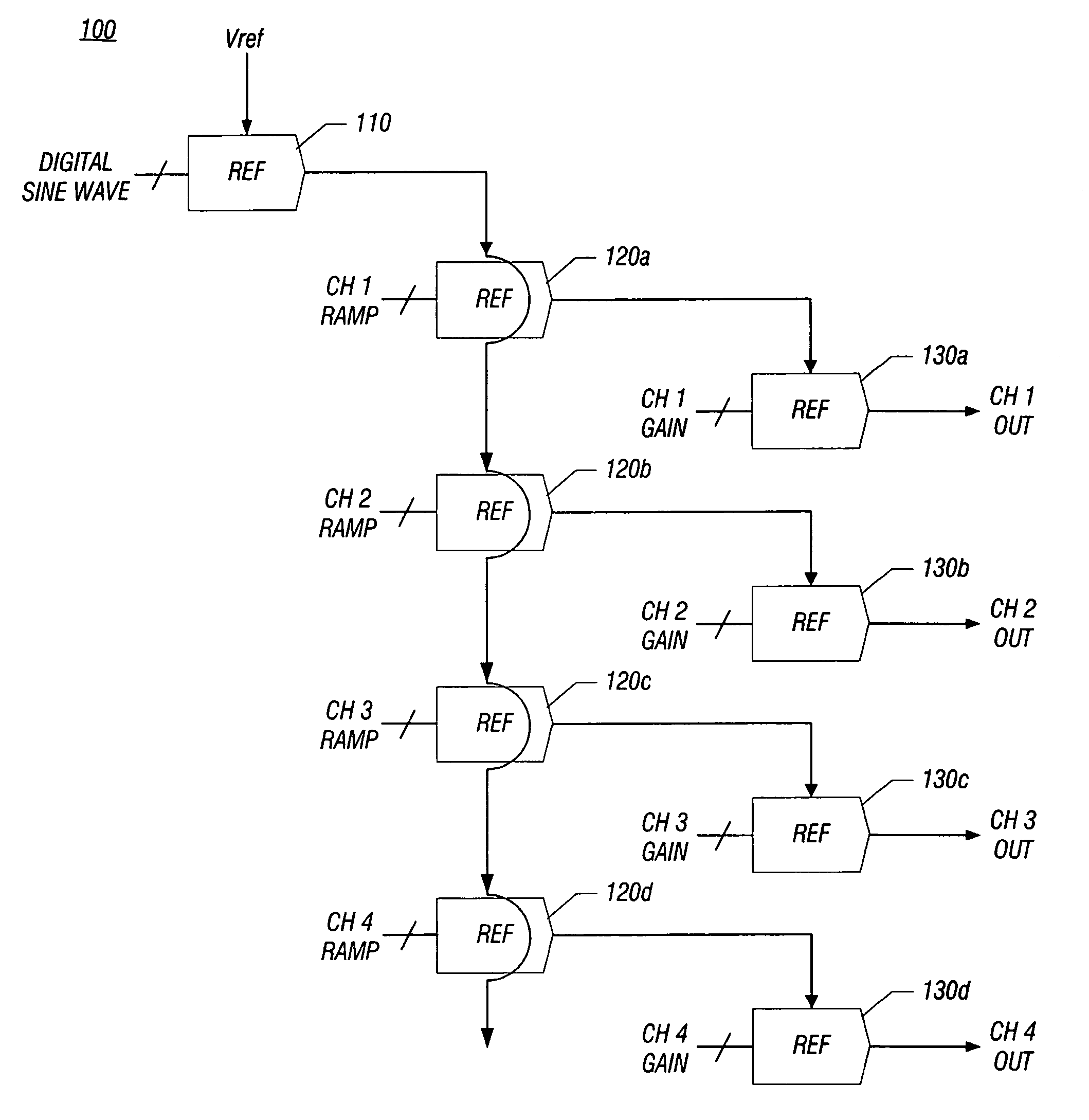
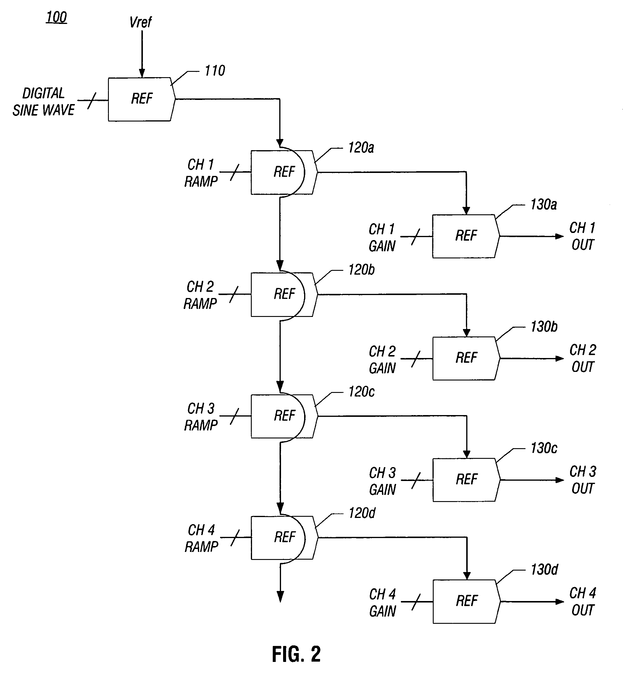
[0028]In various embodiments, a SLIC may include relatively inexpensive DACs to generate meter pulses. Specifically, lower resolution DACs than DACs used for audio processing may be used for purposes of pulse metering. That is, separate pulse metering and audio paths may be provided in a SLIC. Furthermore, the pulse metering path may use different DACs than the audio path.

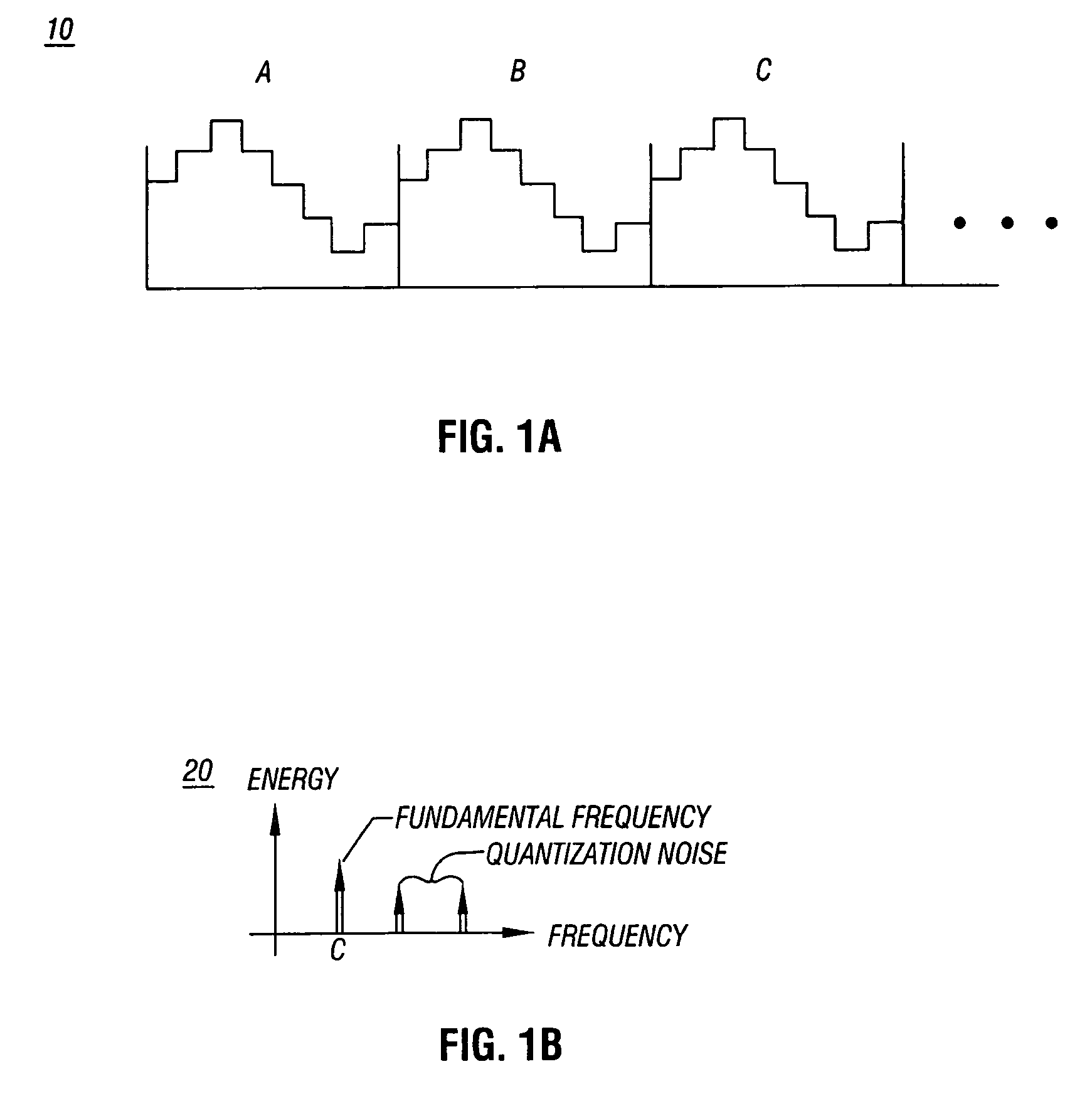
[0029]Such lower resolution DACs may be used in the pulse metering path, as quantization noise does not affect the audio path for several reasons. First, the quantization noise does not affect the audio path because there are two separate paths provided. Furthermore, quantization noise does not affect audio signals because the quantization noise present in a digitally generated sine wave is tonal. That is, because the digitally generated sine wave is substantially coherent (or identical) period-to-period (in other words, is a perfectly periodic signal), the quantization noise does not have subharmonics (or has subs...


PUM


Abstract

In one embodiment, a subscriber line interface circuit includes circuitry to generate metering pulses for insertion onto a subscriber line. The circuitry includes an audio path and a pulse metering path, where the pulse metering path includes a metering generator to generate a digital sine wave from a plurality of stored values, a first interpolator to interpolate the digital sine wave, a filter to filter the interpolated digital sine wave, and a second interpolator to interpolate the filtered interpolated digital sine wave.

Description

FIELD OF THE INVENTION[0001]The present invention relates to the field of telecommunications, and more particularly to a subscriber line interface circuit (SLIC).BACKGROUND[0002]Subscriber line interface circuits are typically found in a central office exchange of a telecommunications network. A SLIC provides a communications interface between the digital switching network of the central office and an analog subscriber line. The analog subscriber line connects to a subscriber station or telephone instrument at a location that is remote from the central office exchange.[0003]The analog subscriber line and subscriber equipment (e.g., a telephone) form a subscriber loop. The interface requirements of a SLIC typically cause high voltages and currents for control signaling with respect to the subscriber equipment on the subscriber loop. Voiceband communications are typically low voltage analog signals on the subscriber loop. Accordingly, the SLIC performs various functions with respect t...

Claims


Application Information

Patent Timeline
Patent Type & Authority Patents(United States)
IPC IPC(8): H04M15/00H04M1/00
CPCH04M15/00
Inventor MILLS, MICHAELGOLDENBERG, MARIUSZHOU, YANWHALEY, JEFFREY
Owner SILICON LAB INC
Why Eureka
Try Eureka