Liquid evaporator

a liquid evaporator and liquid technology, applied in the direction of coke oven details, steam generation using steam absorption, combustion air/fuel air treatment, etc., can solve the problem of reducing the humidification capacity, the heat-up time of the humidification system is relatively long, and the effect of disturbing the quality of artificial respiration

Inactive Publication Date: 2011-08-09
DRAGERWERK AG
View PDF3 Cites 46 Cited by
  • Summary
  • Abstract
  • Description
  • Claims
  • Application Information

AI Technical Summary

Benefits of technology

[0006]Accordingly, the object of the present invention is to improve a liquid evaporator, so that its design is further simplified and, in particular, no pump is needed for its operation any longer.
[0009]The liquid evaporator according to the invention advantageously may have no mobile parts. The liquid to be evaporated is delivered into the evaporator tube by capillary forces. The capillary pump consists of a porous material, especially sintered glass or sintered ceramic (Al2O3), which is in connection with the liquid to be evaporated. To guarantee the back pressure independence of the respiration side following in the downstream direction, the section acting as a capillary wick must be provided with relatively fine pores withstand a respiration pressure of 100 mbar, it is possible, for example, to use sintered elements with a porosity of P16 according to ISO 4793 with a mean pore diameter of 10 μm to 16 μm for the section acting as a capillary wick if water is used as the liquid to be evaporated. The increase in the contact areas between the section acting as a capillary wick and the evaporator tube, which is heated from the outside and consists of a sintered metal or a porous sintered ceramic with a porosity of, for example, P100 with a mean pore diameter of 40 μm to 100 μm, is achieved especially by extending the section acting as a capillary wick into the evaporator section, for example, in a conical shape. The energy of evaporation is thus transmitted not only from the upper section of the liquid evaporator, but also through the lateral or jacket surface to the section acting as a capillary wick, so that the evaporation capacity is substantially increased. A gas-tight jacket in the upper area of the section of the liquid evaporator, which section acts as a capillary wick, optionally ensures good sealing against the environment.

Problems solved by technology

These humidifiers have high resistance and high compliance, which has a disturbing effect on the quality of artificial respiration.
In addition, these humidifying systems have a relatively long heat-up time because the humidifier must first heat up the total amount of water present in the evaporator chamber before the humidifier can reach the desired humidification capacity.
This may take up to 30 minutes, and the humidification capacity is reduced relatively greatly each time cold water is added, which is disadvantageous for the respiration therapy.
It is disadvantageous in this connection that the mechanical components must be replaced after a certain time because of wear.
The actorics components must be made of materials that are resistant to anesthetics, which causes high costs.
The drawback of this arrangement is the necessary pump to dispense the quantity of water.
Thus, there are parts subject to wear, which must be regularly replaced by the user.

Method used


Image

  • Liquid evaporator
  • Liquid evaporator
  • Liquid evaporator

Examples


Embodiment Construction

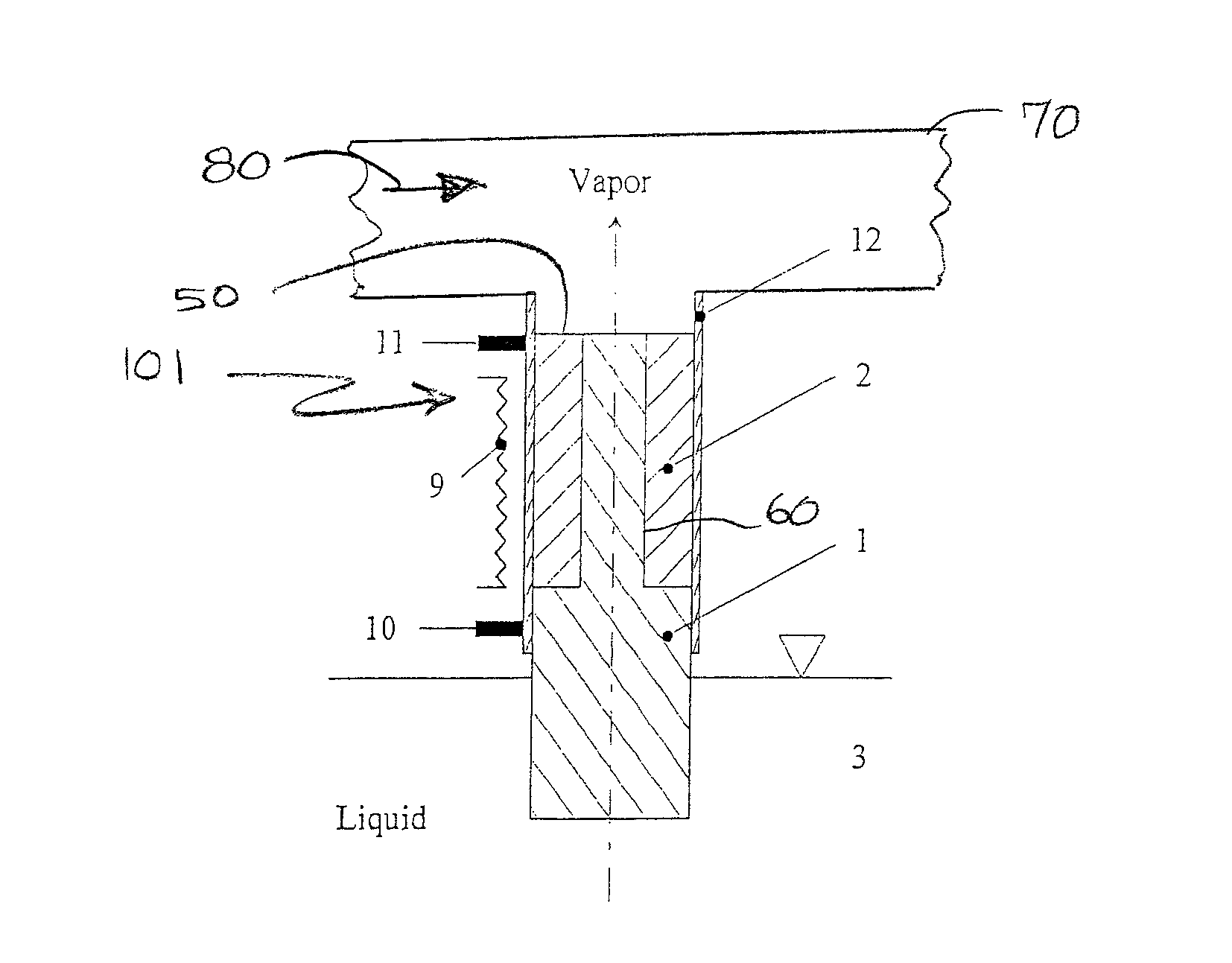
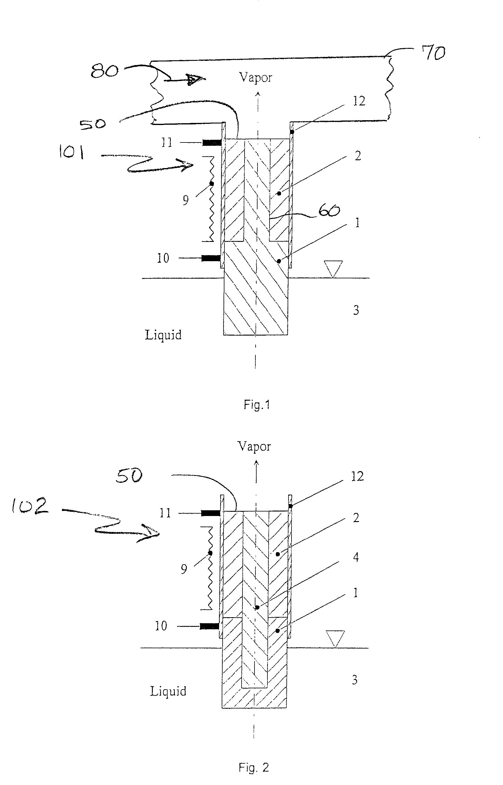
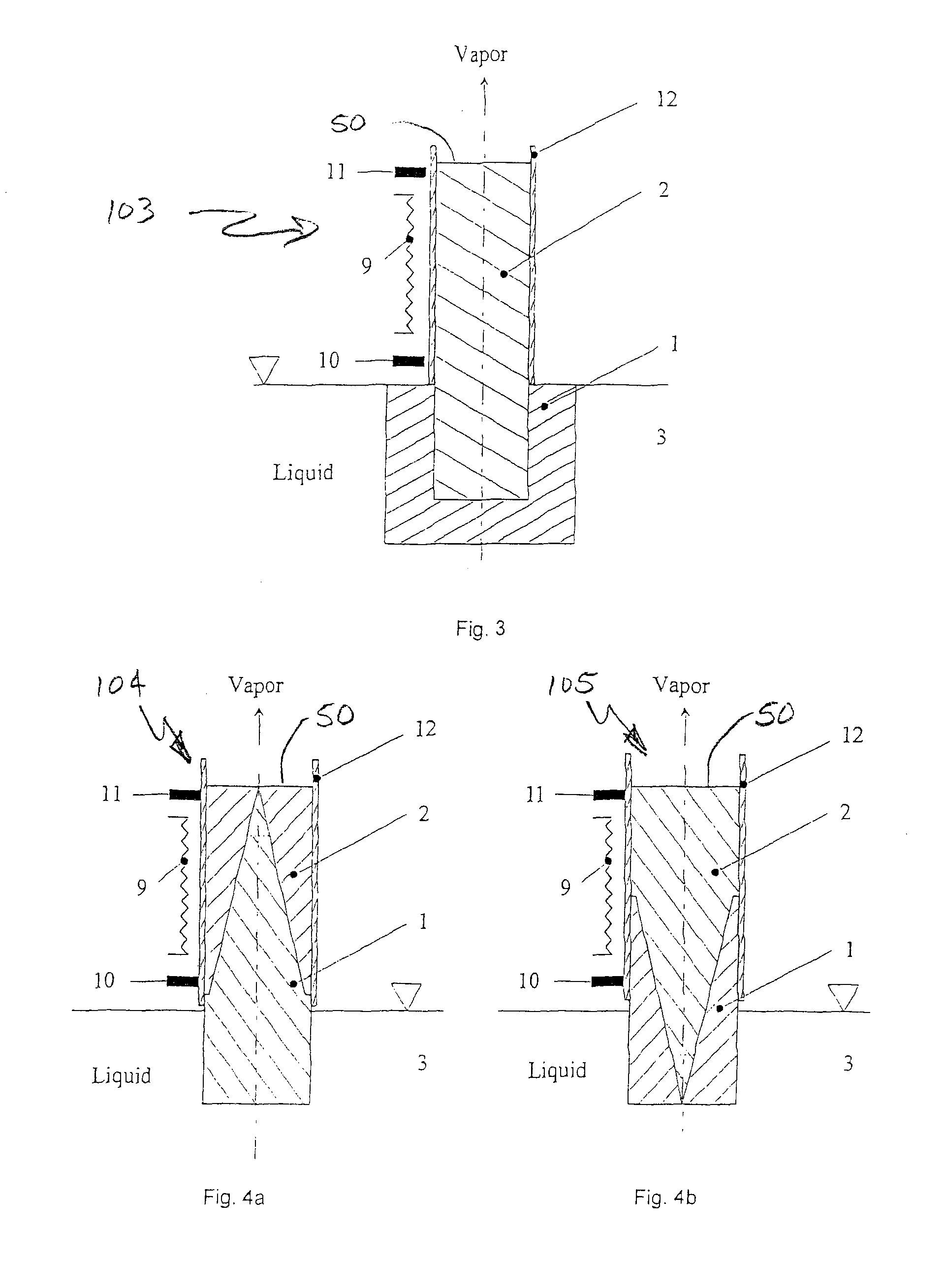
[0022]Referring to the drawings in particular, the invention comprises a liquid evaporator generally designated 101-110 in FIGS. 1-7a. The liquid evaporators 101-110 include a liquid reservoir 3 with a liquid to be evaporated, a heater 9 and an evaporator tube 12. The evaporator tube 12 has a first porous element 1 having a first porosity and with an area in contact with the liquid in the liquid reservoir 3. The evaporator tube 12 also has a second porous element 2 with an area present on an evaporator side 50 used to dispense the evaporated liquid. The tube 12 has an area outside the liquid reservoir heated by the heater 9 which is not directly in connection with the liquid. The first porous element 1 and the second porous element 2 are in contact in contact areas 60 with the first porous element forming a wick delivering liquid from the reservoir to the contact area. The mean pore size of the sintered metal or sintered ceramic (2) which is not directly in connection with the liqui...


PUM

PropertyMeasurementUnit
mean pore sizeaaaaaaaaaa

Abstract

A liquid evaporator includes a liquid reservoir (3) with a liquid to be evaporated, a heater (9) and an evaporator tube (12). The evaporator tube (12) has a first porous element (1) having a first porosity and with an area in contact with the liquid in the liquid reservoir (3) and a second porous element (2) with a second porosity and with an area present on an evaporator side (50) used to dispense the evaporated liquid, and an area outside the liquid reservoir heated by the heater (9) which is not directly in connection with the liquid. The first porous element and the second porous element are in contact in contact areas with the first porous element forming a wick delivering liquid from the reservoir to the contact area.

Description

CROSS REFERENCE TO RELATED APPLICATIONS[0001]This application claims the benefit of priority under 35 U.S.C.§119 of German Patent Application DE 10 2005 054 344.8 filed Nov. 15, 2005 the entire contents of which are incorporated herein by reference.FIELD OF THE INVENTION[0002]The present invention pertains to a liquid evaporator, which is used to dispense an anesthetic or as a breathing gas humidifier for a patient.BACKGROUND OF THE INVENTION[0003]The breathing gas humidifiers used hitherto have, in general, active humidifying systems with heated evaporator chambers, over which the breathing gas to be humidified is sent. These humidifiers have high resistance and high compliance, which has a disturbing effect on the quality of artificial respiration. In addition, these humidifying systems have a relatively long heat-up time because the humidifier must first heat up the total amount of water present in the evaporator chamber before the humidifier can reach the desired humidification ...

Claims


Application Information

Patent Timeline
Patent Type & Authority Patents(United States)
IPC IPC(8): A61M15/00F24F3/14F24F6/08A61H33/06A01G13/06A61M16/00C10B29/00
CPCA61M16/16A61M16/18A61M16/109A61M2205/3372Y10S159/27Y10S159/15Y10S159/28Y10S159/906A61M16/142A61M16/147
Inventor RADOMSKI, KLAUSWRUCK, NORBERTKOCH, JOCHIM
Owner DRAGERWERK AG
Why Eureka
Try Eureka