Vehicle end portion structure

a technology for end portions and vehicles, applied in the field of end portions, can solve the problems of reducing the height difference, and reducing the ability of the sub-frame to absorb the impact, so as to achieve efficient transmission and improve the effect of impact absorption

Inactive Publication Date: 2011-08-09
TOYOTA JIDOSHA KK
View PDF26 Cites 28 Cited by
  • Summary
  • Abstract
  • Description
  • Claims
  • Application Information

AI Technical Summary

Benefits of technology

[0007]This invention thus provides an end portion structure with improved impact absorbability realized by having impact force be efficiently transmitted to a crumple zone of a side member even if another vehicle or the like collides with either the side member or the sub-frame that is fixed to the side member.
[0009]According to this structure, when another vehicle or the like collides with the side member from the longitudinal direction, the sub-frame separates from the side member so as not to inhibit the deformation of the crumple zone in the side member. Also, the sub-frame is mounted to the side member so that external force on the sub-frame from the longitudinal direction is transmitted to the side member. Accordingly, even if the other vehicle or the like collides with the side member or the sub-frame that is fixed to the side member, the force of impact can be efficiently transmitted to the crumple zone of the side member, thus improving the ability to absorb the impact.
[0015]According to the vehicle end portion structure according to the invention, impact force can be efficiently transmitted to a crumple zone of the side member even if another vehicle or the like collides with the side member or the sub-frame that is fixed to the side member, thus improving impact absorbability.

Problems solved by technology

As a result, the crumple zone becomes that much narrower which reduces the ability to absorb the impact.
However, if the sub-frame was not fixed to the side members and another vehicle was to collide with the sub-frame and there was a large difference in height between the two vehicles, for example, the force of impact on the sub-frame would not be able to be transmitted to the side members, which would reduce the ability of the sub-frame to absorb the impact.

Method used


Image

  • Vehicle end portion structure
  • Vehicle end portion structure
  • Vehicle end portion structure

Examples


Embodiment Construction

[0034]Hereinafter, example embodiments of the invention will be described in detail with reference to the accompanying drawings. In the following description, like elements will be denoted by like reference numerals and redundant descriptions will be omitted. Also, the drawings have been simplified so the dimensional proportions of the drawings will not always match the objects in the description.

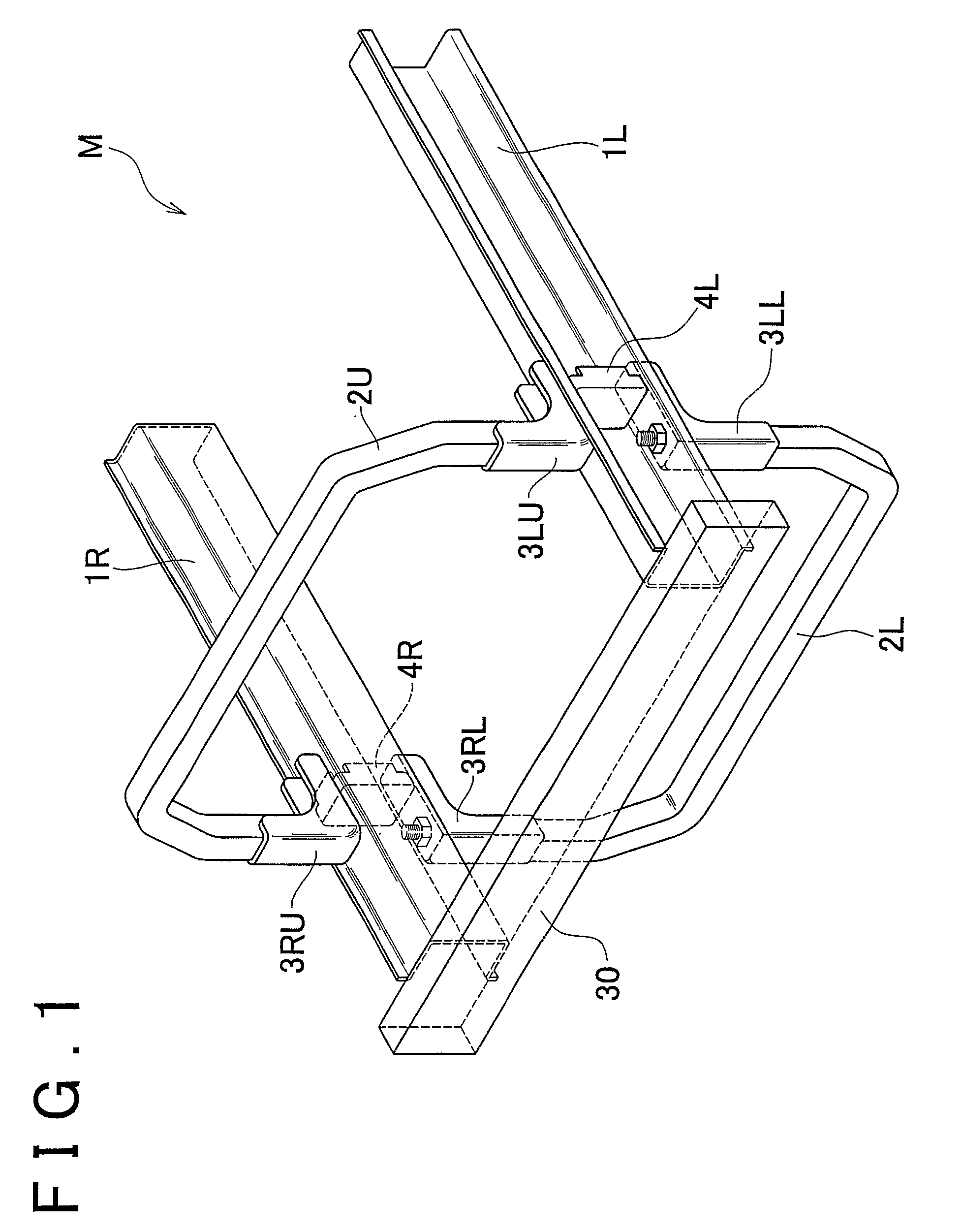
[0035]FIG. 1 is a perspective view of a front portion structure of a vehicle according to a first example embodiment of the invention. As shown in the drawing, a vehicle M according to this example embodiment is provided with a right side member 1R that extends in the longitudinal direction on one end portion in the width direction and a left side member 1L that extends in the longitudinal direction on the other end portion in the width direction. The front end portions of these side members 1R and 1L function as crumple zones (i.e., crushable zones). An upper radiator support 2U and a lowe...


PUM


Abstract

A front end portion of a side member functions as a crumple zone during a collision with another vehicle or the like. A radiator support is attached via a bracket to this crumple zone. When another vehicle or the like collides with the side member, the radiator support separates from the side member. When another vehicle or the like collides with the radiator support, external force applied in the rear direction to the radiator support is transmitted to the side member.

Description

[0001]This is a 371 national phase application of PCT / IB2008 / 000906 filed 21 Jan. 2008, claiming priority to Japanese Patent Application No. 2007-023288 filed 1 Feb. 2007, the contents of which are incorporated herein by reference.FIELD OF THE INVENTION[0002]The invention relates to an end portion (either a front end portion or a rear end portion or both) structure of a vehicle.BACKGROUND OF THE INVENTION[0003]A vehicle structure is known in which a side member that extends in the longitudinal direction of a vehicle is provided on each side portion of the vehicle. The end portion of each side member has a crumple zone (i.e., a crushable zone) provided to absorb impact during a collision or the like. Also, a radiator is provided at the front of the vehicle. This radiator is supported by a radiator support, for example, which is provided so as to connect the crumple zones of both side members. If another vehicle or the like collides with a sub-frame that extends in the lateral (i.e., ...

Claims


Application Information

Patent Timeline
Patent Type & Authority Patents(United States)
IPC IPC(8): B60J7/00
CPCB62D21/155B60R19/48B60R19/023B60R19/04B60R19/24B60R2019/026B60R2019/186
Inventor TAMAKOSHI, KOJI
Owner TOYOTA JIDOSHA KK
Why Eureka
Try Eureka