Glazing inspection

a technology of glazing and inspection, applied in the direction of instruments, material analysis, television systems, etc., can solve the problems of poor pattern reflected from the glazing, low image brightness and contrast, and unreliable patterns produced, and achieve the effect of facilitating a high-speed system

Inactive Publication Date: 2011-08-09
PILKINGTON PLC
View PDF13 Cites 0 Cited by
  • Summary
  • Abstract
  • Description
  • Claims
  • Application Information

AI Technical Summary

Benefits of technology

[0006]In a preferred embodiment the digital means comprises a digital video projector which preferably includes a digital micromirror device (DMD). Such a device is less sensitive to temperature than LCDs and has good image brightness and contrast, and therefore produces more reliable greyscale patterns.
[0012]Preferably, the exposure time of the CCD camera is synchronised with the pulse width modulation period of the digital video projector. Such an apparatus facilitates a high speed system.

Problems solved by technology

Greyscale patterns are commonly generated by transmitting light through LCDs (liquid crystal displays) but this is problematic due to the sensitivity of LCDs to temperature.
Thus at a constant operating voltage the optical contrast varies with changes in temperature, which can lead to unreliable patterns being produced.
In addition, LCDs have a relatively low image brightness and contrast and so the quality of the pattern reflected from the glazing is poor and may cause difficulties in obtaining reliable results.

Method used


Image

  • Glazing inspection
  • Glazing inspection
  • Glazing inspection

Examples


Embodiment Construction

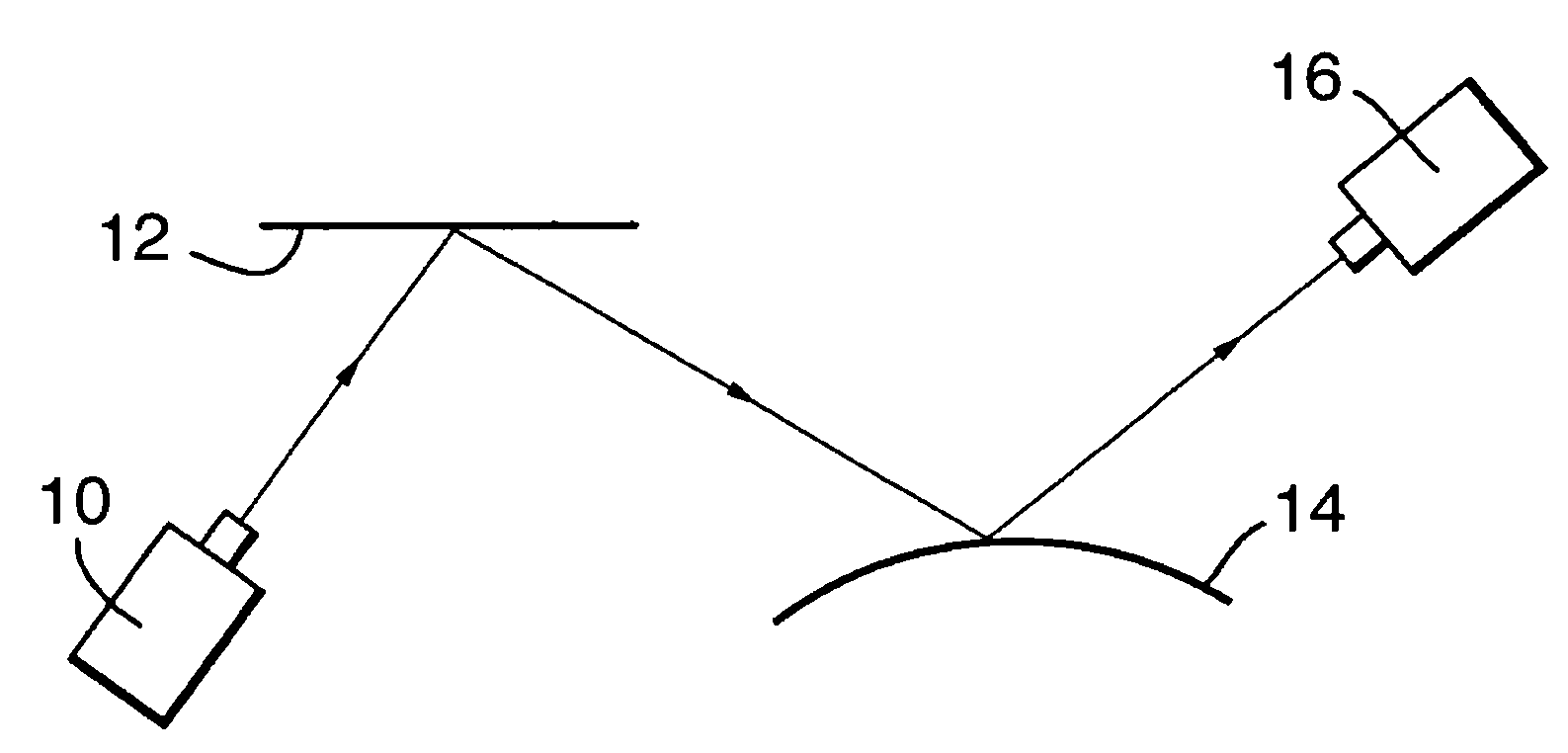
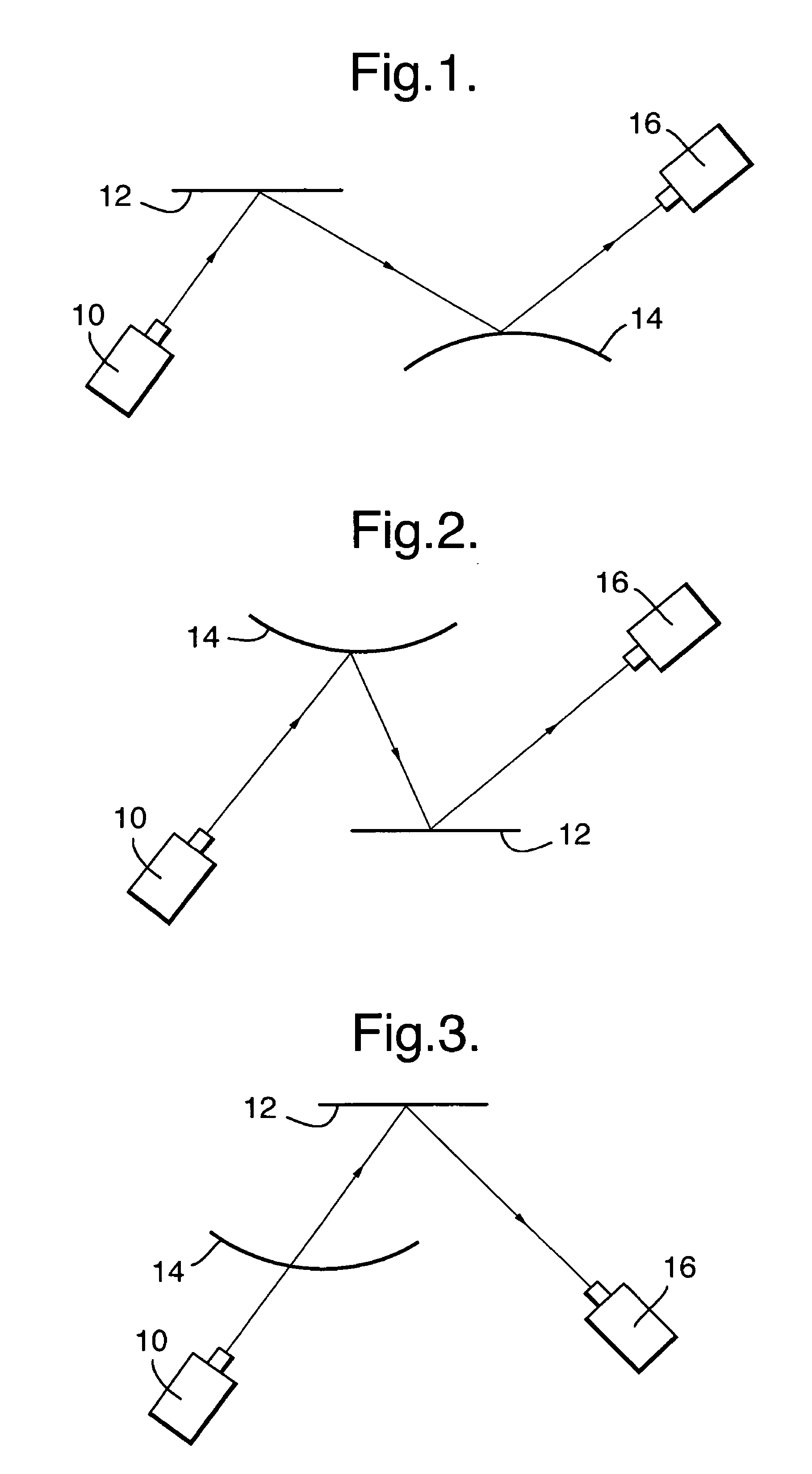
[0021]FIGS. 1 and 2 illustrate an arrangement of apparatus according to an embodiment of the invention for determining the optical quality of a glazing in reflection. In FIG. 1 a digital video projector 10 projects a sinusoidal greyscale pattern onto screen 12. A CCD camera 16 captures images of the greyscale pattern as reflected off glazing 14, which is shown as being curved but may be flat. FIG. 2 illustrates an alternative arrangement where the digital video projector 10 projects a sinusoidal greyscale pattern directly onto the glazing 14 which reflects it onto screen 12 and CCD camera 16 captures images of the reflected greyscale pattern from the screen 12.

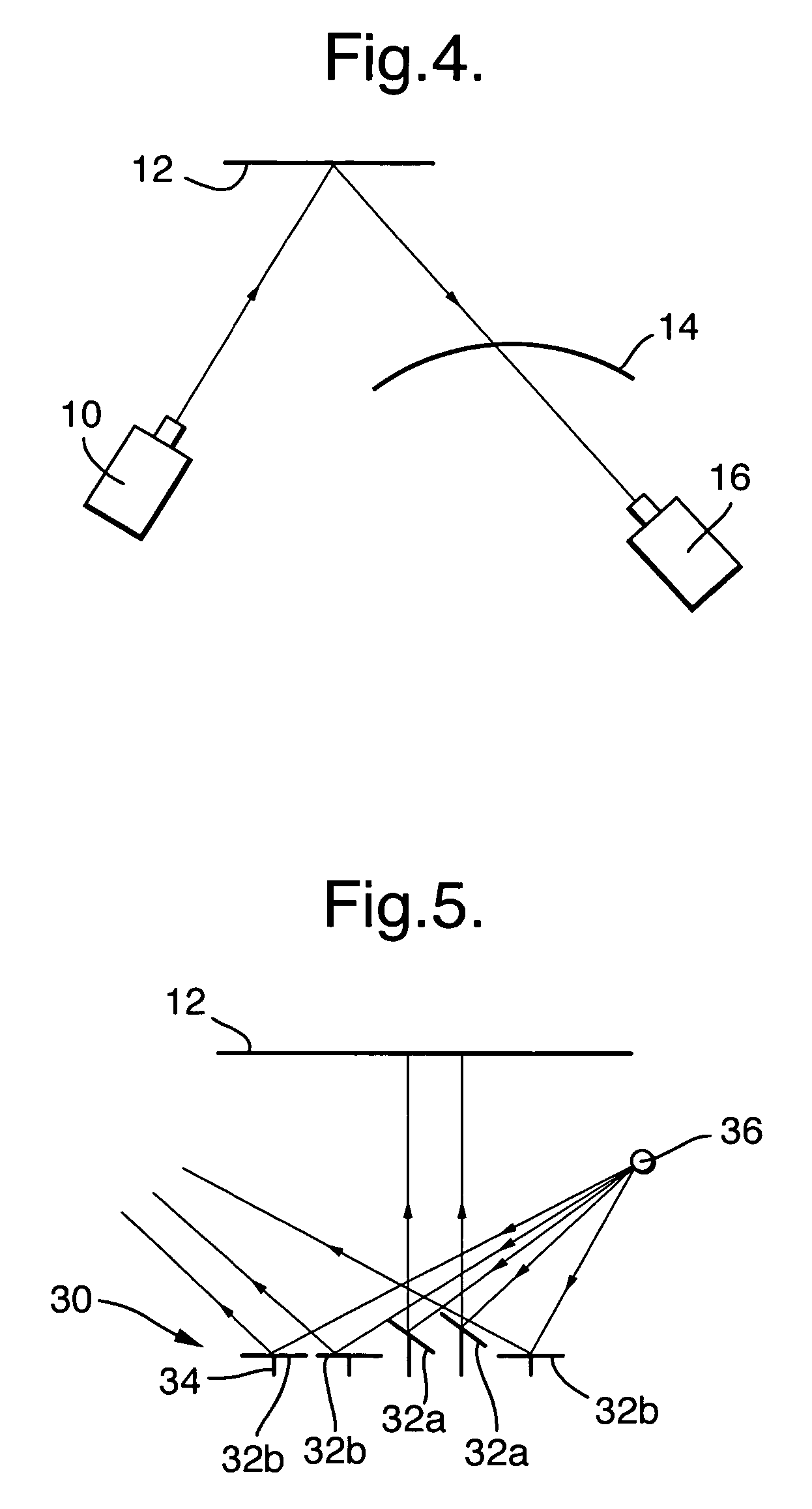
[0022]FIGS. 3 and 4 illustrate an arrangement of apparatus according to an embodiment of the invention for determining the optical quality of a glazing in transmission. In FIG. 3 a digital video projector 10 projects a sinusoidal greyscale pattern through a glazing 14 onto screen 12. A CCD camera 16 captures images of the grey...


PUM

PropertyMeasurementUnit
exposure timeaaaaaaaaaa

Abstract

A method and apparatus for inspection of the optical quality of a glazing is provided. A greyscale image is generated digitally, and reflected off or transmitted through a glazing, and captured using an image capture device. Preferably, the generation of the greyscale pattern and the capturing of the reflected or transmitted greyscale pattern are synchronised.

Description

FIELD OF THE INVENTION[0001]This invention relates to glazing inspection, in particular to a method and apparatus for determining the optical quality of a glazing in reflection or transmission, in particular a vehicle glazing, in which a greyscale pattern is either reflected off the product or transmitted through it and captured, and then subsequently processed.DESCRIPTION OF THE PRIOR ART[0002]In the production of vehicle glazings it is desirable to inspect every glazing to determine its optical quality, to ensure that it is acceptable for use as a vehicle glazing. One such inspection technique involves a method of capturing an image of a greyscale pattern reflected off a vehicle glazing and subsequently processing the image, is disclosed in EP1061357.[0003]Greyscale patterns are commonly generated by transmitting light through LCDs (liquid crystal displays) but this is problematic due to the sensitivity of LCDs to temperature. As the temperature decreases the LCD fluid requires a ...

Claims


Application Information

Patent Timeline
Patent Type & Authority Patents(United States)
IPC IPC(8): H04N7/18G01N21/896G01N21/958
CPCG01N21/958G01N2021/9586
Inventor DAY, STEPHEN ROLAND
Owner PILKINGTON PLC
Why Eureka
Try Eureka