Method for finding the prediction direction in intraframe video coding

Active Publication Date: 2011-08-09
FRANCE TELECOM SA
View PDF7 Cites 0 Cited by
  • Summary
  • Abstract
  • Description
  • Claims
  • Application Information

AI Technical Summary

Benefits of technology

[0012]Accordingly, one object of the present invention is to provide, in an intraframe video coding process that calculates virtual blocks associated with a current image block in given prediction directions, a method of find

Problems solved by technology

However, it has the disadvantage that image compression is not so good.
However, because of its complexity, entailing calculating al

Method used


Image

  • Method for finding the prediction direction in intraframe video coding
  • Method for finding the prediction direction in intraframe video coding
  • Method for finding the prediction direction in intraframe video coding

Examples


Example

DETAILED DESCRIPTION OF THE DRAWINGS

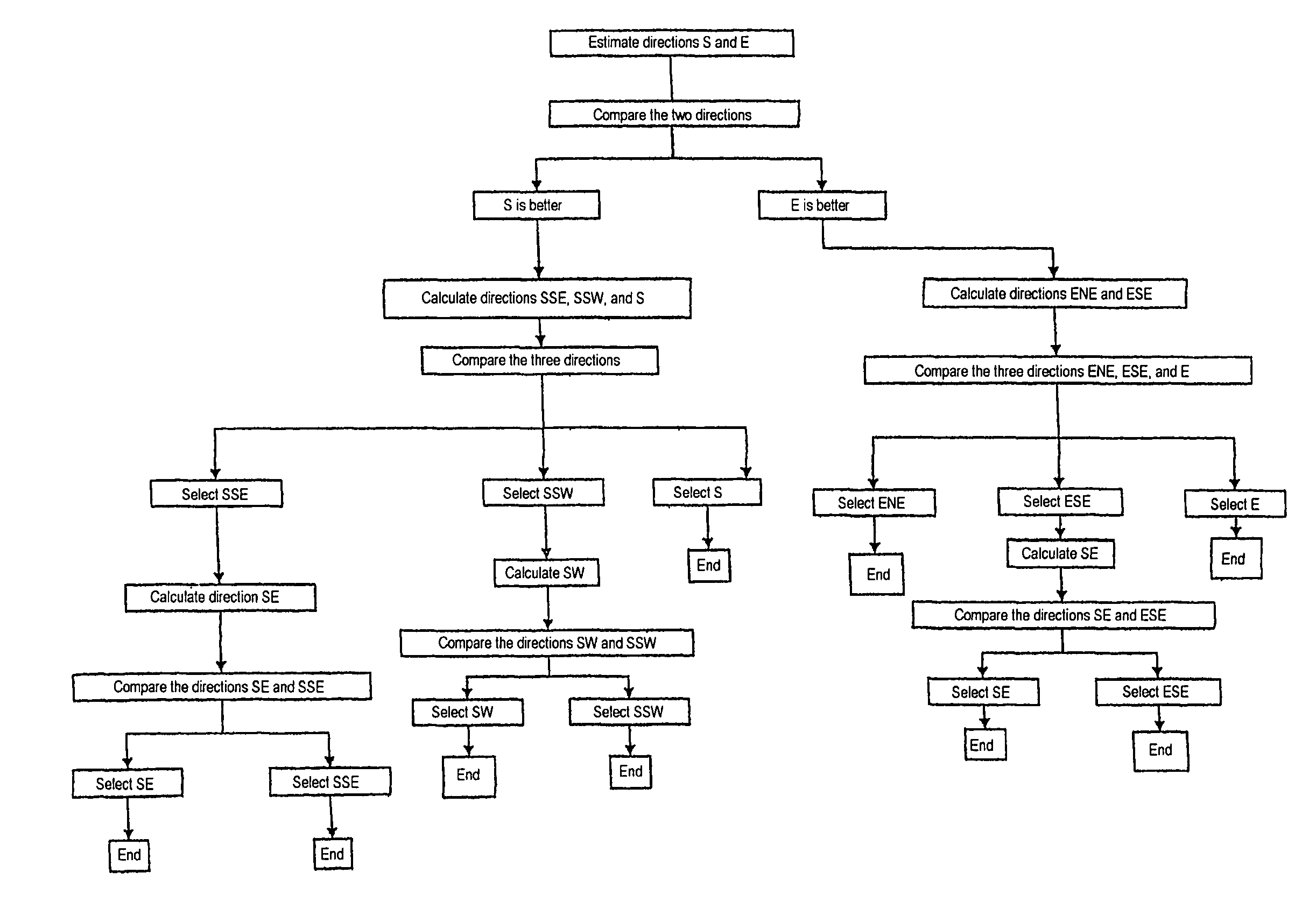
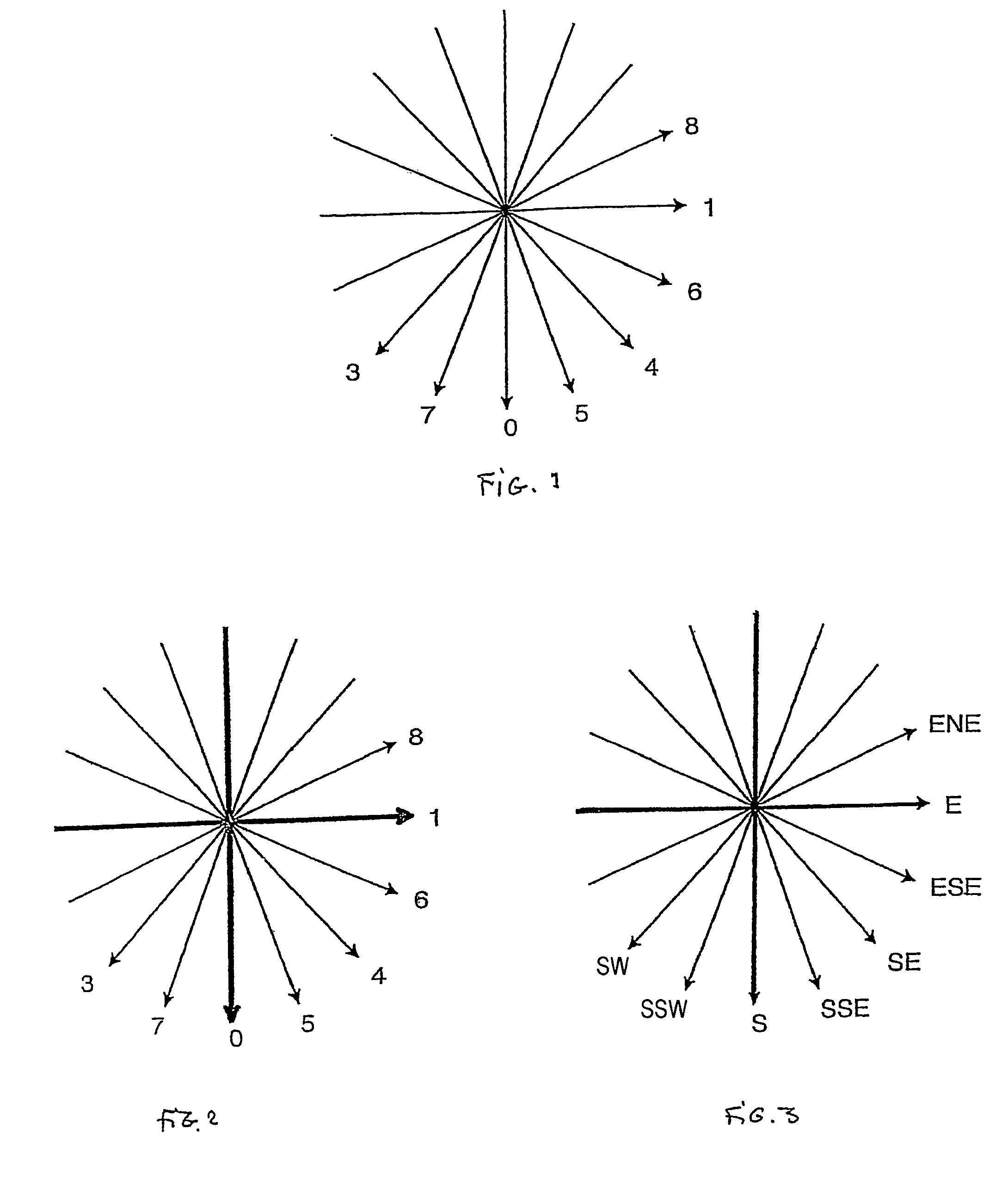
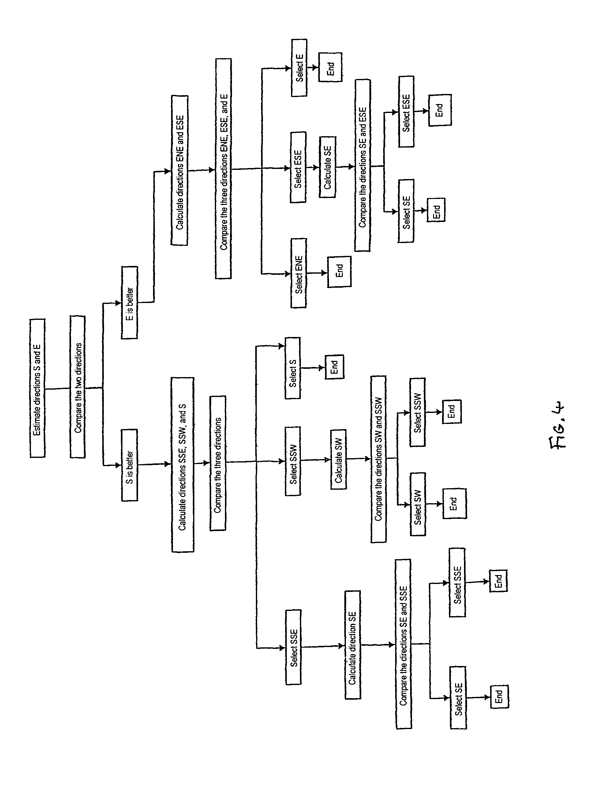
[0032]FIG. 1 represents the eight prediction directions of the H.264 / MPEG-4 AVC standard for calculating eight virtual blocks of a current block, including the virtual block having the least difference with respect to the current block that will determine the best prediction direction, i.e. the direction that will be used for intraframe coding of the image.

[0033]The best prediction direction comparison calculation may be effected in various ways, for example by calculating the sum of the absolute value differences between the pixels being coded and the corresponding prediction. The sums obtained can then be compared and only the smallest sum retained.

[0034]FIG. 3 shows the correspondence between the FIG. 1 prediction directions and the names of those directions used below.

[0035]The first step of the method of the invention firstly selects from the eight prediction directions two starting prediction directions, called the initial directions.

[0036]A...


PUM


Abstract

A method of finding the prediction direction during intraframe video image coding. The method comprises the following steps: selecting two initial prediction directions (E, S), calculating virtual blocks associated with said initial prediction directions (E, S), comparing said virtual blocks with the current block and selecting the initial prediction direction (E), which is then called the first main direction, calculating virtual blocks associated with the prediction directions (ENE, ESE) immediately adjacent to said first main direction (E), comparing said virtual blocks with the current block to determine the best prediction direction, if the best prediction direction is the first main direction (E) or one direction (ENE) of the immediately adjacent directions situated at one extremity of the set of prediction directions, deciding this best direction is the required prediction direction, otherwise, calculating the virtual block associated with the prediction direction (SE) other than the first main direction (E) that is immediately adjacent to the second main direction (ESE), comparing said virtual blocks with the current block to determine the best prediction direction, if said best prediction direction is said second main direction (ESE) or the immediately adjacent direction (SE) situated at one extremity of the set of prediction directions, deciding that best direction is the required prediction direction, otherwise, continuing the process iteratively until the required prediction direction is found. Application to video coding.

Description

RELATED APPLICATION[0001]This is a U.S. national stage of application No. PCT / FR2005 / 000195, filed on 31 Jan. 2005.FIELD OF THE INVENTION[0002]The present invention relates to a method of finding the prediction direction in intraframe video coding.[0003]One particularly advantageous application of the invention is to intraframe video coding as defined in the H.264 / MPEG-4 AVC standard.BACKGROUND OF THE INVENTION[0004]Video coding an image generally consists in effecting on that image operations known as compression, with the aim of facilitating the transmission of the image over telecommunications networks by reducing the quantity of data to be transmitted, at the same time as attempting to obtain a final reproduced image of the best possible quality.[0005]Interframe image coding essentially consists in establishing the difference between a current image and an image predicted from preceding images. Only the difference is transmitted, which represents a high level of compression sinc...

Claims


Application Information

Patent Timeline
IPC IPC(8): H04N11/02H04N7/26H04N19/593
CPCH04N19/105H04N19/176H04N19/20H04N19/136H04N19/192H04N19/593H04N19/11
Inventor LORAS, FREDERICAMIEL, JEAN-CHRISTOPHE
Owner FRANCE TELECOM SA
Why Eureka
Try Eureka