Real-time physics engine enhanced computing method, medium and system based on neural network

A neural network and physics engine technology, which is applied in the field of real-time physics engine enhancement and neural network-based systems, can solve problems such as large amount of calculation, and achieve the goal of improving point and surface density, fast, accurate and efficient physical collision calculation, and shortening calculation time. Effect

Active Publication Date: 2021-02-23
DUNYU SHANGHAI INTERNET TECH CO LTD
View PDF9 Cites 0 Cited by
  • Summary
  • Abstract
  • Description
  • Claims
  • Application Information

AI Technical Summary

Problems solved by technology

Although high-density parallel computing can be achieved with the help of proprietary hardware calculators, the area density and the density of computing hardware will inevitably increase, and the amount of calculation will be large

Method used


Image

  • Real-time physics engine enhanced computing method, medium and system based on neural network
  • Real-time physics engine enhanced computing method, medium and system based on neural network
  • Real-time physics engine enhanced computing method, medium and system based on neural network

Examples


Embodiment 1

[0052] figure 1 It is a schematic flow chart of an embodiment of the neural network-based real-time physics engine-enhanced computing method in an embodiment.

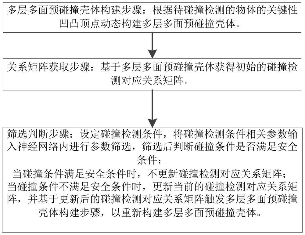
[0053] Such as figure 1 As shown, in this embodiment, the calculation method based on the neural network-based real-time physics engine enhancement includes steps:

[0054] Multi-layer and multi-face pre-collision shell construction steps: dynamically construct multi-layer and multi-face pre-collision shells according to the key concave-convex vertices of the object to be detected for collision;

[0055] Relation matrix acquisition step: obtain the initial collision detection corresponding relationship matrix based on the multi-layer and multi-face pre-collision shell;

[0056] Screening and judging step: setting the collision detection conditions, inputting the relevant parameters of the collision detection conditions into the neural network for parameter screening, and judging whether the collision conditions meet ...

Embodiment 2

[0072] image 3 A schematic flow diagram of another embodiment of the neural network-based real-time physics engine-enhanced computing system according to the present invention is schematically shown.

[0073] Such as image 3 As shown, in this embodiment, the pre-collision polygon is generated according to the model volume and shape of the object to be collided with and its shape at the current moment, but the number of faces of the generated pre-collision polygon is relatively small, which is similar to rough And an invisible safe appearance, according to the accuracy requirements, use the neural network calculation method to convert into an approximate multi-layer pre-collision body (that is, the multi-layer multi-faceted pre-collision body in this case), considering that each object surface has two layers of safety Distance, the maximum and minimum safety distance, therefore, the definition of the minimum safety distance is that the safety distance of the first outer pre-...


PUM


Abstract

The invention discloses a neural network-based calculation method for real-time physical engine enhancement, which includes the steps of: building a multi-layer and multi-face pre-collision shell: dynamically constructing a multi-layer and multi-face pre-collision according to the key concave-convex vertices of objects to be detected for collision Shell; relationship matrix acquisition step: obtain the initial collision detection correspondence relationship matrix based on the multi-layer and multi-face pre-collision shell; screening and judgment step: set the collision detection condition, input the relevant parameters of the collision detection condition into the neural network for parameter screening, screening Finally, judge whether the collision condition meets the safety condition; when the collision condition meets the safety condition, the collision detection correspondence matrix is ​​not updated; Collision shell. In addition, the present invention also discloses a computer-readable storage medium storing a computer program and a computing system enhanced by a neural network-based real-time physics engine.

Description

technical field [0001] The present invention relates to the field of physics, in particular to a neural network-based system, medium and method. In particular, it relates to a system, medium and method for enhancing a neural network-based real-time physics engine Background technique [0002] Scenes such as engineering mechanics, driving simulation, material simulation, and clothing digital try-on need to follow Newton's laws of mechanics and laws of gravity, and use physics engines to achieve results close to the real natural world. With the help of many physical models in the physics engine, especially the real-time collision detection in many physical models is one of the most common and consumes the most calculation time. The most closely related is the area and number of surface triangles of multiple objects to be collided. [0003] The current collision usually adopts the method of point-to-plane distance calculation, but when the area becomes larger or the fixed poin...

Claims


Application Information

Patent Timeline
Patent Type & Authority Patents(China)
IPC IPC(8): G06N3/063
CPCG06N3/063G06F30/27G06N3/02G06F17/16
Inventor 赵凤萍
Owner DUNYU SHANGHAI INTERNET TECH CO LTD
Why Eureka
Try Eureka