Railway joint connection arrangement

a rail and connection arrangement technology, applied in the direction of runways, rope railways, roads, etc., can solve the problems of not allowing sufficient lateral centering, no biasing force could be generated in the lower flange, and undesired lateral offset of the rails, etc., to achieve effective arrangement

Inactive Publication Date: 2011-08-16
STAHL CRANESYSTEMS GMBH
View PDF26 Cites 14 Cited by
  • Summary
  • Abstract
  • Description
  • Claims
  • Application Information

AI Technical Summary

Benefits of technology

[0009]It is an object of the present invention to provide a more effective arrangement for joining rails of an overhead conveyor in end-to-end relation to each other.
[0011]In carrying out the invention, the rail joint connector arrangement for the lower flange, two abutment pieces are provided that are introduced into the respective lower flanges which are constructed with a hollow profile. Thus, on either side of the rail joint, there is an abutment piece in the lower flange, and this is secured in the axial direction. Each abutment exhibits an end face pointing in the direction toward the rail joint. In the area of the two end faces, the abutment pieces are provided with centering means that guarantee an exactly aligned orientation of the abutment pieces, independent of the tensioning means. The lateral play that the abutment pieces have in the lower flange also is reduced.
[0012]Furthermore, tensioning means are provided to tension the two abutment pieces relative to each other. In this way, any gap at the rail joint in the area of the lower flange can be avoided. The running surface of the rail is thus smooth and continuous. Wear of the wheels of the trolley traveling gear thereby is reduced to a minimum and is not worsened by the rail joint.
[0017]In terms of production, the centering means can be effected very easily if they involve centering boreholes and alignment pins. Therefore, the abutment pieces can be formed easily and exactly on NC machines. Complicated milling work is eliminated.

Problems solved by technology

Thus, the problem arises of connecting the individual rail sections at the joints so that the traveling trolley moves in jerk-free fashion across the rail joint.
A lateral offset of the rails is also undesired because side guide wheels of the traveling gear could catch on these parts, or could bump against the resulting step.
A disadvantage in this construction is that no biasing forces could be generated in the lower flange transverse to the separation plane of the joint.
At the upper flange, the abutment pieces in this location do not allow sufficient lateral centering.
Centering by the tensioning bolt is usually not sufficient.
The use of such a construction in the area of the lower flange would be inadequate since the centering or correctly positioned fixing of the two rail ends at the joint is not adequately assured.

Method used


Image

  • Railway joint connection arrangement
  • Railway joint connection arrangement
  • Railway joint connection arrangement

Examples


Embodiment Construction

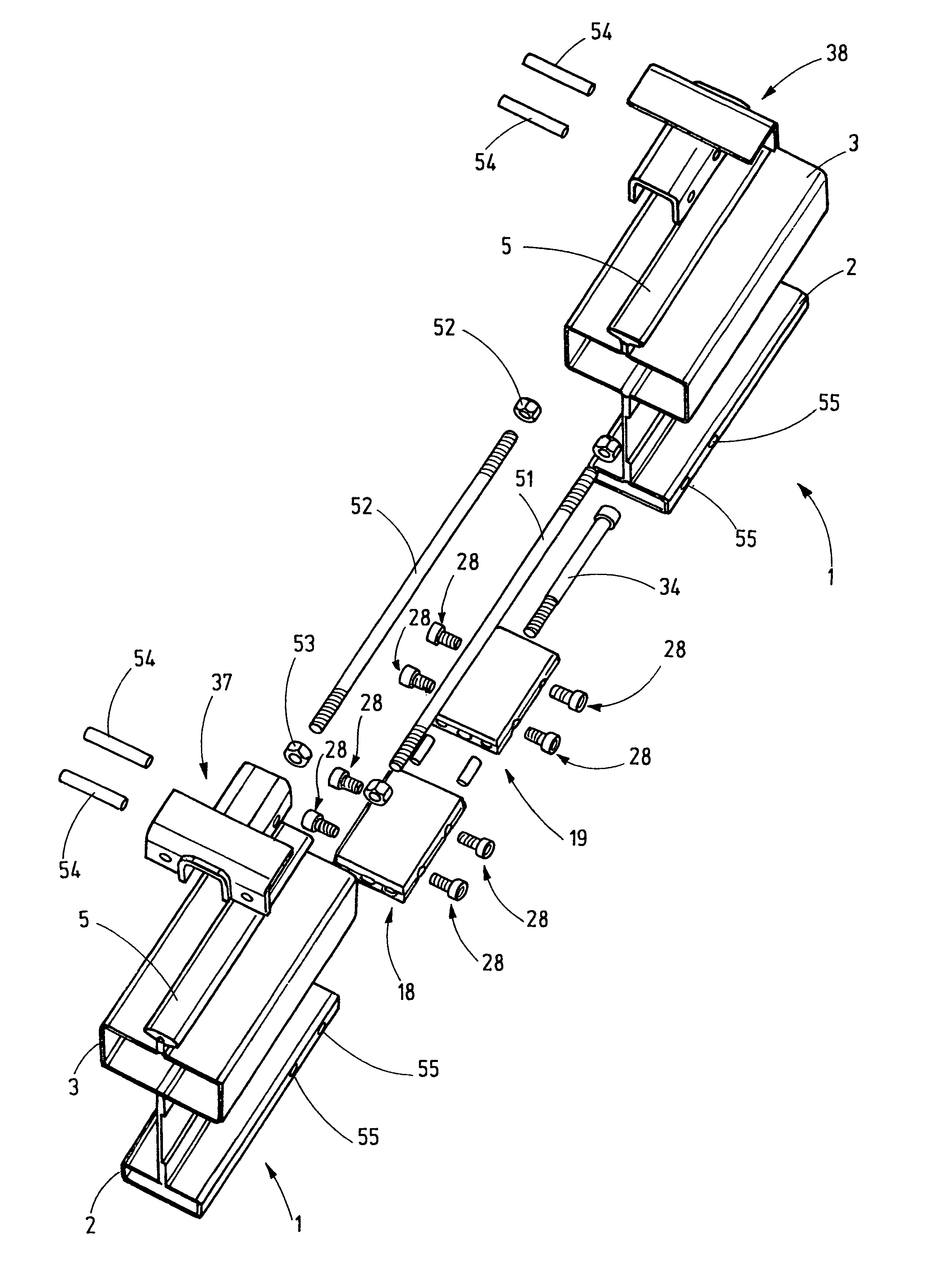
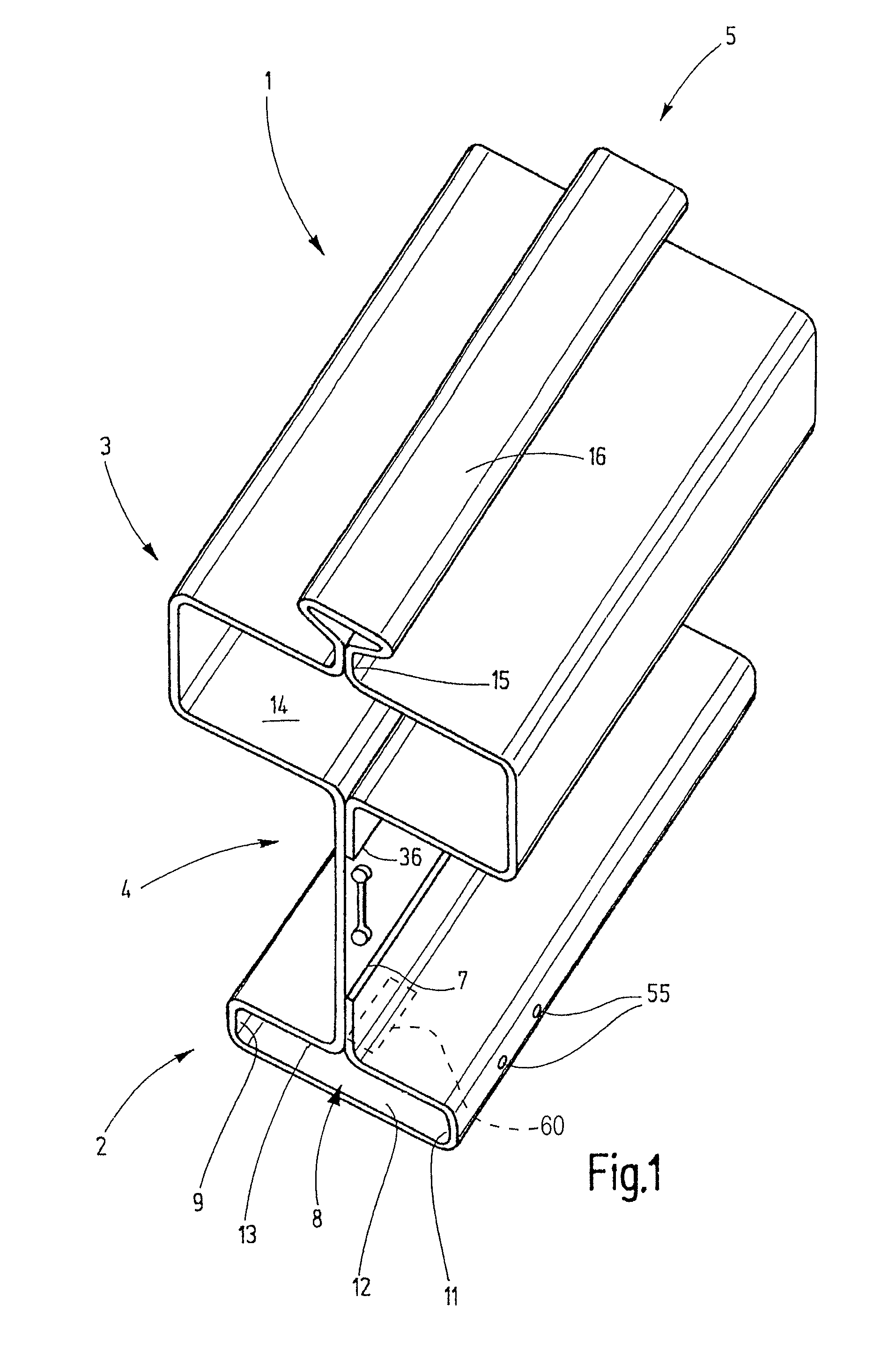
[0028]Referring now more particularly to FIG. 1 of the drawings, there is shown an illustrative running rail 1 for an overhead conveyor. The running rail 1 has a lower flange 2 and an upper flange 3. The upper and lower flanges 2, 3 are connected to each other by a web 4. On the top side of the upper flange 3, there is a support rib 5. The web 4 lies in the vertical plane of symmetry.

[0029]The entire running rail 1 has a constant cross section that is continuous over the length and made from a roll-formed steel plate whose edges 6, 7 are laser-welded to the web 4. As a result of the roll-formed profile, the lower flange 2 is formed as a hollow chamber that defines a hollow space 8 that is rectangular in cross section. The hollow space 8 is bounded by two narrow sides 9, 11 of the lower flange 2, a bottom side 12, and a top side 13 from the center of which the web 4 projects. The upper flange 3 is similarly constructed as a hollow chamber which defines a hollow space, also with a rec...


PUM


Abstract

A joint connector for the lower flanges of adjoining running rails is assembled from two abutment pieces that each is seated in a lower flange of a respective rail that forms the joint. By use of centering devices, the correctly aligned positioning of the two abutment pieces is assured, wherein the abutment pieces transfer their aligned positioning to the lower flanges that meet each other without offset at the joint and the positioning cannot be negatively affected by transverse forces. The connection also provides a positive-fit in a transverse direction of the rails. Another joint connector arrangement connects the two running rails in the region of the top side. Abutment pieces in this case are seated as riders on a support rib and are connected to each other by tension rods.

Description

CROSS-REFERENCE TO RELATED APPLICATIONS[0001]This patent application is the national phase of PCT / EP2007 / 010021, filed Nov. 20, 2007, which claims the benefit of German Patent Application No. DE 102006058422.8, filed Dec. 8, 2006.FIELD OF THE INVENTION[0002]The present invention relates generally to a connector arrangement for connecting rails in adjoining and end-to-end relation to each other, and more particularly, to a connector arrangement for connecting joints in rails for overhead conveyors.BACKGROUND OF THE INVENTION[0003]In overhead conveyors, trolleys of hoists run on rails that are suspended from the ceiling. Continuous rails can be used for short distances. For longer distances, the rails must be divided for assembly and production-related reasons. Thus, the problem arises of connecting the individual rail sections at the joints so that the traveling trolley moves in jerk-free fashion across the rail joint.[0004]Furthermore, the joint connector arrangement that bridges th...

Claims


Application Information

Patent Timeline
Patent Type & Authority Patents(United States)
IPC IPC(8): B61B3/00
CPCB66C7/14E01B25/24
Inventor HESS, WILFRIED
Owner STAHL CRANESYSTEMS GMBH
Why Eureka
Try Eureka