De-oiler system for an aircraft engine

a technology of aircraft engine and oil tank, which is applied in the direction of machines/engines, mechanical equipment, separation processes, etc., can solve the problems of increasing oil consumption, and achieve the effect of improving the rate at which lubricating oil is recycled, without significantly complicating the structur

Active Publication Date: 2011-08-23
SN DETUDE & DE CONSTR DE MOTEURS DAVIATION S N E C M A
View PDF24 Cites 8 Cited by
  • Summary
  • Abstract
  • Description
  • Claims
  • Application Information

AI Technical Summary

Benefits of technology

[0007]An object of the present invention is to provide a de-oiler system for an aircraft engine enabling improvement of the rate at which lubricating oil is recycled, i.e. the rate at which oil is separated from air, without significantly complicating the structure, e.g. of the rear bearing enclosure of the aircraft engine.
[0014]Preferably, the axes of said hollow rotary axle and of said hollow rotary shaft are parallel. Thus, implementing the transmission is significantly simplified.

Problems solved by technology

It is found that with such a system, the rate at which oil is separated from the air is significantly less than the target rate, and that this gives rise to increase oil consumption.

Method used


Image

  • De-oiler system for an aircraft engine
  • De-oiler system for an aircraft engine
  • De-oiler system for an aircraft engine

Examples


Embodiment Construction

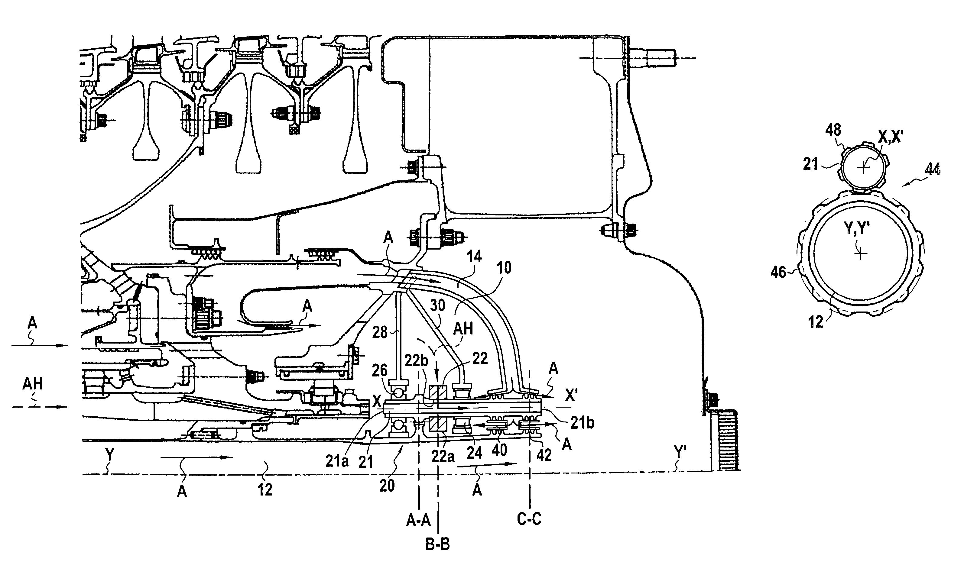
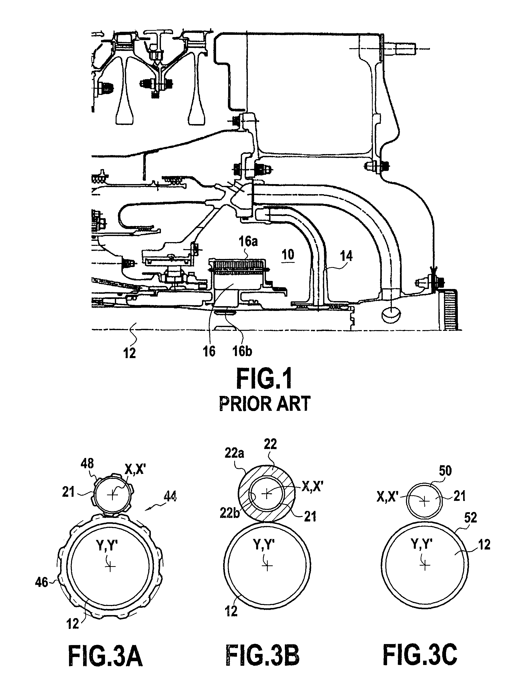
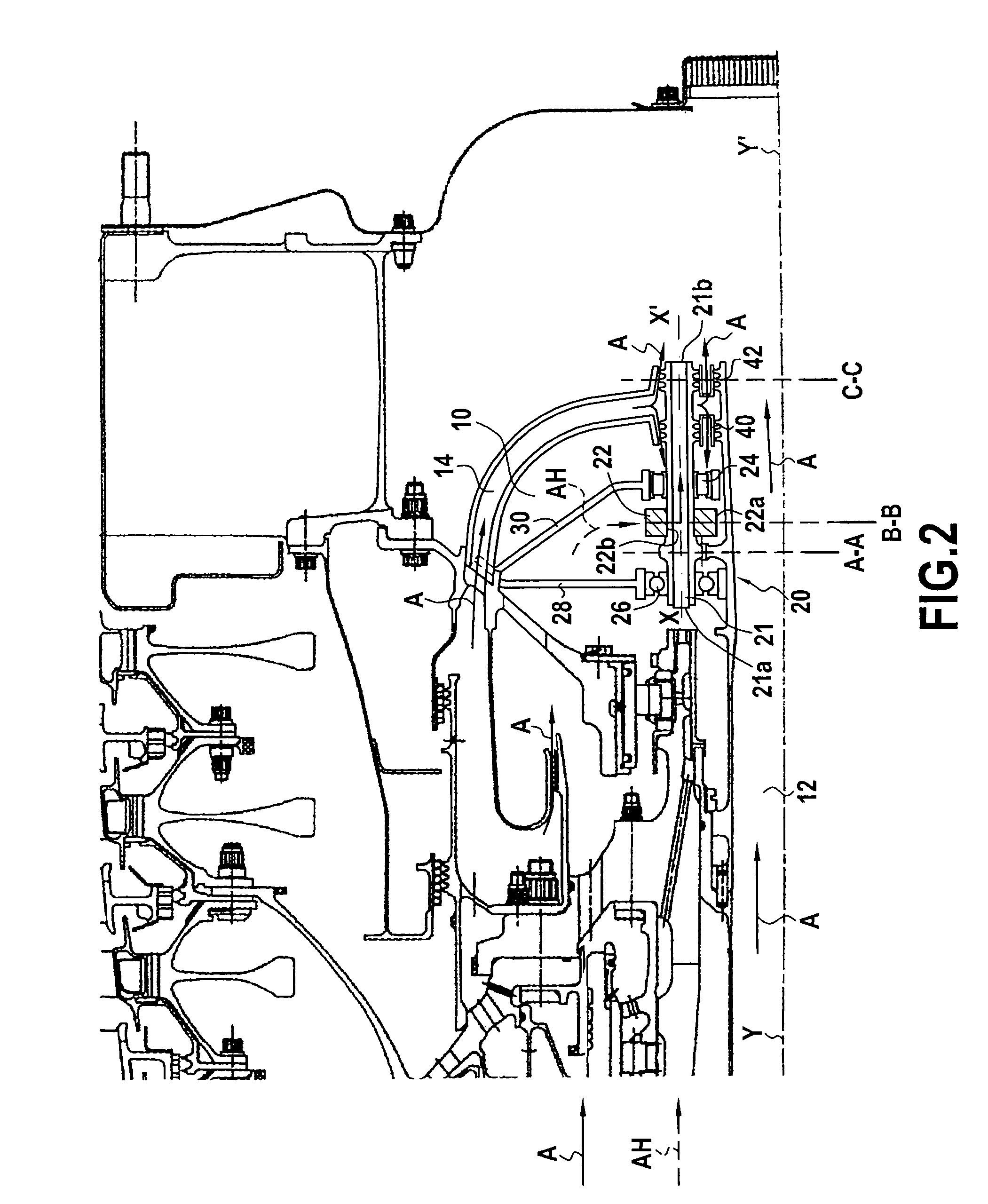
[0026]With reference to FIGS. 2, 3A, 3B, and 3C, there follows a description of the general organization of a de-oiler structure in accordance with the invention, mounted in the rear bearing enclosure 10 of an aircraft engine, or more precisely of a turbojet. In this figure, there can be seen once more not only the rear bearing enclosure 10, but also the hollow rotary shaft 12 coming from a front bearing enclosure, and air flow is represented by arrows A, while air-oil mixture flow is represented by arrows AH.

[0027]The de-oiler structure given overall reference 20 is essentially constituted by a hollow rotary axle 21 having an annular centrifugal de-oiler structure 22 mounted thereon. The hollow rotary axle 21 is preferably mounted in such a manner that its axis XX′ is parallel to the axis YY′ of the hollow rotary shaft 12. Nevertheless, these axes need not be mutually parallel. The hollow rotary axle 21 is mounted into two series of bearings 24 and 26, themselves mounted into suppo...


PUM

PropertyMeasurementUnit
volumeaaaaaaaaaa
speedaaaaaaaaaa
annular shapeaaaaaaaaaa

Abstract

A de-oiler system for an aircraft engine including a casing defining a volume containing a rotary shaft and a mixture of air and oil for processing is disclosed. The system includes a hollow rotary axle; a de-oiler structure fastened to the hollow rotary axle and rotating together with the hollow rotary axle, the de-oiler structure having an inlet first face communicating with the volume and an outlet second face connected to a passage formed in the hollow rotary axle; and a transmission device between the hollow rotary axle and the rotary shaft for communicating to the hollow rotary axle a speed of rotation V about its axis in such a manner that the speed of rotation V is greater than a speed of rotation v of the rotary shaft.

Description

[0001]The present invention relates to a de-oiler system for an aircraft engine and to an aircraft engine including such a de-oiler system. In an aircraft engine, particularly a turbojet, oil flows are circulated toward certain components to perform lubrication functions. After being introduced into components that need lubrication, the oil is recovered, recycled, and re-injected into the oil flows of the lubrication circuit.[0002]Nevertheless, lubrication circuits are not completely leak resistant resulting in losses that define oil consumption of the engine.BACKGROUND OF THE INVENTION[0003]The main source of oil leakage is found in the system for de-oiling the air from engine enclosures associated with the front and rear bearings of the engine: air flows to the bearing enclosures between parts that are rotary and stationary, and air picks up oil that is subsequently vented to the outside through a de-oiler system. Increasing the air / oil separation power of the de-oiler system make...

Claims


Application Information

Patent Timeline
Patent Type & Authority Patents(United States)
IPC IPC(8): B01D46/18
CPCB01D45/14F01D25/18F05D2260/4031F05D2240/50F05D2240/61F01M2013/0422
Inventor EARITH, THOMAS JULIEN ROLANDGAUTHIER, GERARD PHILIPPEMORREALE, SERGE RENE
Owner SN DETUDE & DE CONSTR DE MOTEURS DAVIATION S N E C M A
Why Eureka
Try Eureka