Preform for optical element and optical element

a technology of optical elements and molds, applied in the field of optical elements, can solve problems such as unstableness, and achieve the effects of reducing the percent of defective molds and prolonging the mold li

Inactive Publication Date: 2011-08-23
OHARA
View PDF14 Cites 11 Cited by
  • Summary
  • Abstract
  • Description
  • Claims
  • Application Information

AI Technical Summary

Benefits of technology

[0010]The present invention provides a preform for an optical element which enables prolongation of lifetimes of molds in a series of steps of manufacturing an optical glass element and enables reduction in percent of generation of defective molding articles and which can be produced according to a simple method, and provides a method of manufacturing the same.
[0012]According to these embodiments, it is expected that upon pressing with a convex pressing die or a concave pressing die in the following molding step, the aforementioned concave face or convex face may match this convex pressing die or concave pressing die, or fit thereto, thereby allowing the pressing force of the pressing die to be uniformly applied to the preform. Furthermore, the preform does not usually have a projection or the like that engages with another member or component, and its settling position may be mostly determined by gravitation and shearing force resulting from compressive force, frictional force and the like applied from the surface to be brought into contact. Furthermore, how it is settled may decide whether it is stable (stable against some variation) or unstable (unstable because some variation causes further greater variation). It is likely to be unstable when the shape of the pressing die is different from the shape of the face of the preform to be in contact. Therefore, a preferable shape of the preform and contact with the pressing die will allow the pressing force of the pressing die to be uniformly applied to the entirety in either case of the pressing die having a convex shape or the pressing die having a concave shape. Hence, because of favorable settlement of the preform, occurrence of defective molding articles may be reduced.
[0017]When the top surface and the under surface of the preform both have a shape including a convex face, it is preferred that the ratio of wall thickness of the preform in the vicinity of approximately the central position of the convex face of the top surface and the under surface to the aforementioned diameter be 0.45 or less. Also, this ratio is more preferably 0.1 or greater. Moreover, this ratio is preferably 0.3 or less. When the ratio falls within this range, occurrence of chipping of the manufactured preform can be reduced, and in addition, pressing time can be shortened due to a small amount of deformation.

Problems solved by technology

Furthermore, how it is settled may decide whether it is stable (stable against some variation) or unstable (unstable because some variation causes further greater variation).
It is likely to be unstable when the shape of the pressing die is different from the shape of the face of the preform to be in contact.

Method used


Image

  • Preform for optical element and optical element
  • Preform for optical element and optical element
  • Preform for optical element and optical element

Examples


example 1

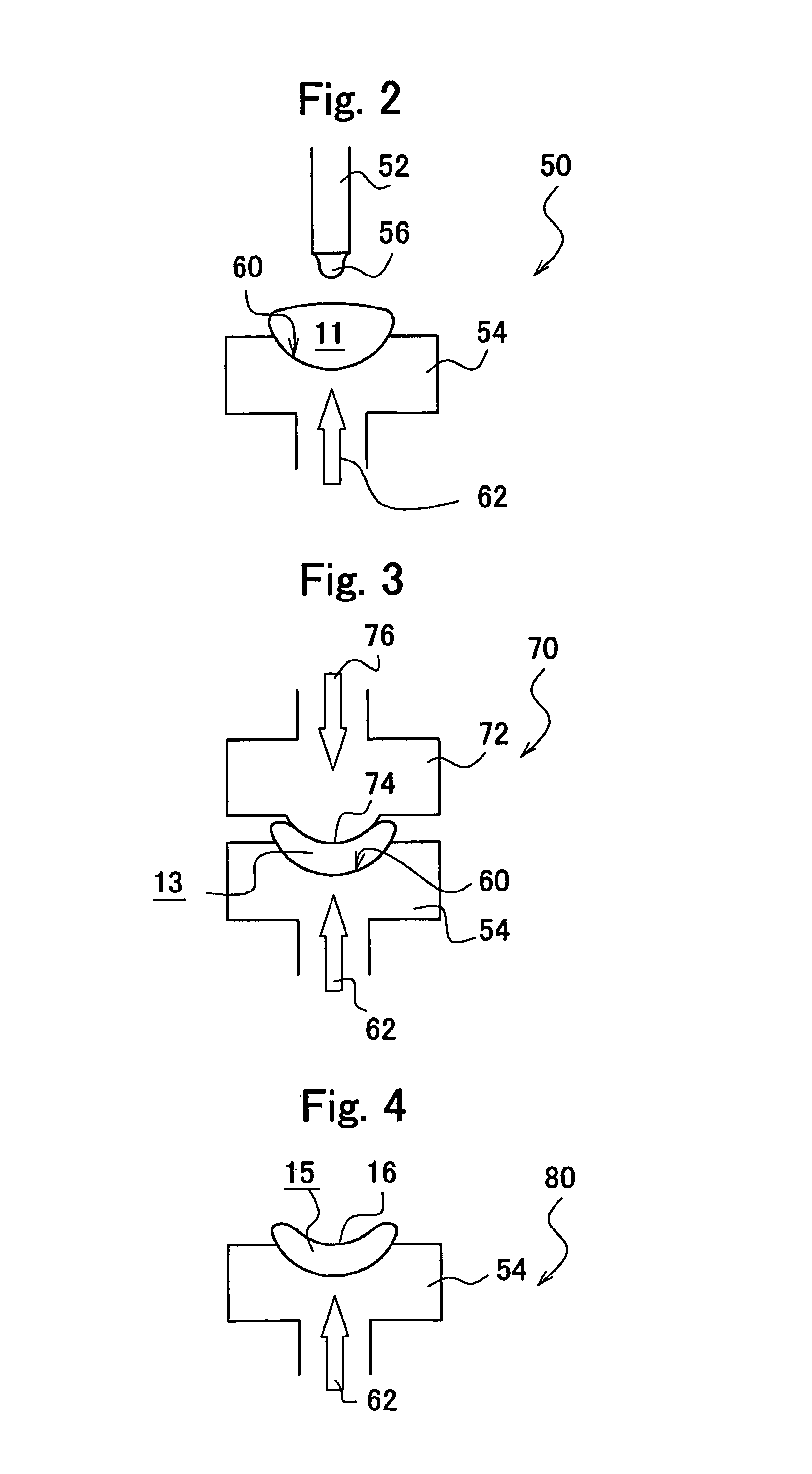
[0083]Melting was conducted in a glass melting furnace to give the glass melting temperature of 1100 to 1300° C., while a nozzle 52 at the leading end of a pipe was heated at a temperature of 900 to 1200° C. Next, a lower mold half 54 was disposed immediately below the nozzle 52, and a glass block 11 was dropped, or elevated to approach the nozzle 52. When the concave molding face of the lower mold half 54 was filled with the molten glass accordingly, the lower mold half 54 was lowered. The molten glass was cut then to obtain a glass block 11.

[0084]The material of the lower mold half 54 was a porous metal, and emits any one of inert gases such as air, oxygen, nitrogen, argon and the like or any mixed gas thereof at 0.5 to 10 L / min. The lower mold half 54 holding the glass block 11 was pressed with the upper mold half 72 to obtain a preform for an optical element 13 having a concave part. In this example, two kinds, i.e., a silica-boric acid based or lanthanum-based optical glass wer...

example 2

[0085]A glass block 11 was obtained with a lower mold half 54 with no emission of a gas under a temperature condition that is similar to Example 1. The lower mold half 54 holding this glass block 11 was moved immediately below an upper mold half 72 provided with fine pores that emit the gas, and simultaneously, was pressed by a pressing face 74 of the upper mold half 72 disposed at an opposing position under a condition of the glass surface temperature of 800 to 1150° C. Thus, a preform for an optical element 13 having a concave part was obtained.

[0086]In the pressing method, pressing against an open face of the glass block 11 was serially conducted for 1 to 10 sec. Surface of the preform for an optical element 13 having a concave part obtained according to this method was a smooth mirror face.

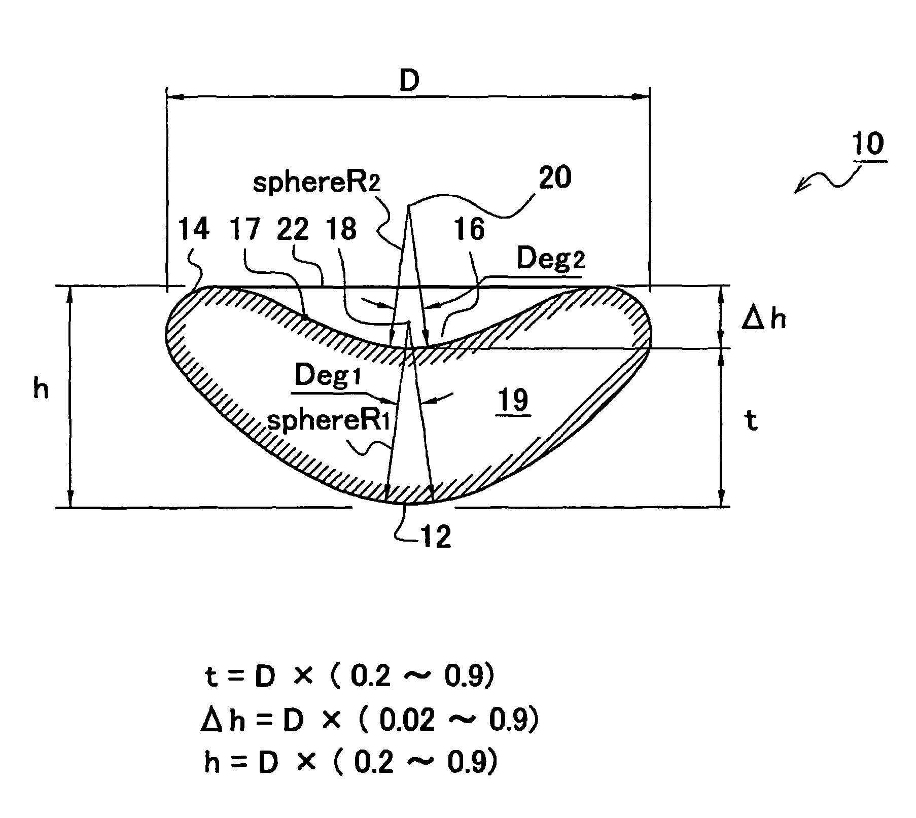
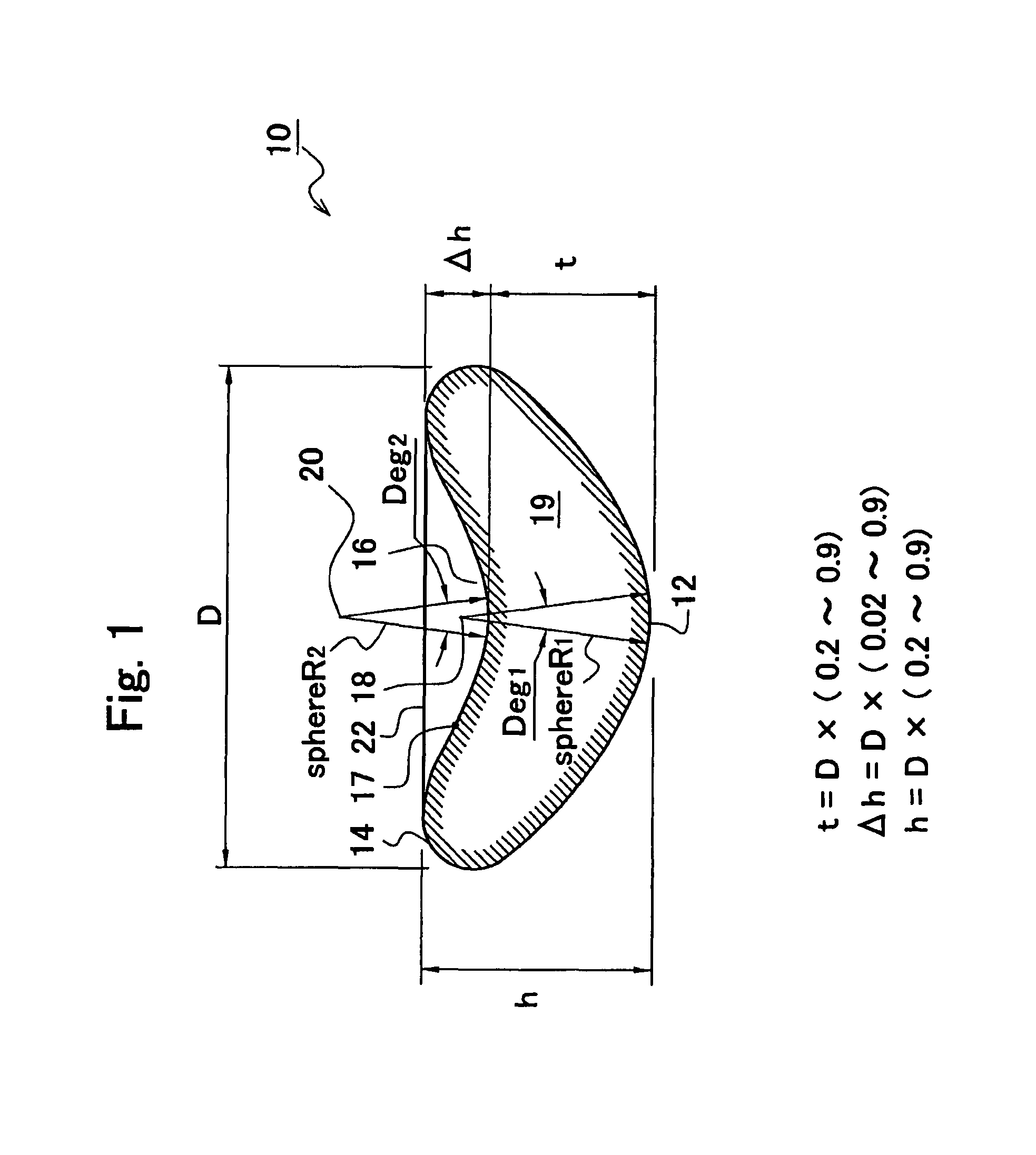
[0087]The glass preform produced in this manner had a center wall thickness being 0.3 times of the external diameter, a depth of the concave part being 0.06 times of the external diameter, and...

example 3

[0088]A preform for an optical element having a biconcave part was obtained through manufacturing according to a similar method to Example 1 except that the lower mold half in Example 1 was changed to a lower mold half having a convex shape. In this Example, two kinds, i.e., a silica-boric acid based or lanthanum-based optical glass were used as an optical glass composition.


PUM

PropertyMeasurementUnit
diameteraaaaaaaaaa
diameteraaaaaaaaaa
diameteraaaaaaaaaa

Abstract

A preform for an optical element is provided which involves less amount of deformation of glass in molding, and readily improves lifetime of the mold. The present preform for molding an optical glass element 10 exhibits an almost circular shape having a predetermined diameter in top view, exhibits a flattened semicircular shape having a predetermined overall height in side view, has a concave face on the top surface such that the predetermined overall height is attained at approximately the central position of the aforementioned circular shape, and has a concave face so as to fit along the convex face of the top surface such that a space is provided on the bottom face. The under surface may be either a concave face or a convex face. Also, the top surface may be either a concave face or a convex face.

Description

[0001]This application is based on and claims the benefit of priority from Japanese Patent Application No. 2004-359591, filed on 13 Dec. 2004, Japanese Patent Application No. 2005-047276, filed on 23 Feb. 2005, and Japanese Patent Application No. 2005-187810, filed on 28 Jun. 2005, the content of which are incorporated herein by reference.TECHNICAL FIELD[0002]The present invention relates to a preform for an optical element for molding optical elements such as lenses and the like used in optical equipment, and to a method for manufacturing the same.BACKGROUND ART[0003]In recent years, optical lenses molded to have a predetermined shape have been used as lenses for digital cameras and the like, and concave lenses as well as biconcave lenses have become common optical components. In light of precise and large-scale manufacture of these optical lenses, methods in which a preliminary molding is produced first by molding a molten glass material to have a shape as approximate as possible ...

Claims


Application Information

Patent Timeline
Patent Type & Authority Patents(United States)
IPC IPC(8): C03B11/08G02B3/00G02B1/00
CPCC03B11/08C03B40/04Y10T428/21C03B2215/48C03B2215/47Y02P40/57C03B11/00
Inventor ISHIZAKI, FUTOSHIFUKUDA, SHIGEKISUGIZAKI, KENJI
Owner OHARA
Why Eureka
Try Eureka