Blind spot detection system and method using preexisting vehicular imaging devices

a technology of preexisting vehicles and blind spots, applied in the field of vehicular blind spots detection, can solve problems such as complex systems and retrofitting to existing vehicles

Inactive Publication Date: 2011-08-23
GENTEX CORP
View PDF19 Cites 31 Cited by
  • Summary
  • Abstract
  • Description
  • Claims
  • Application Information

AI Technical Summary

Problems solved by technology

Electrical implementations for blind spot monitoring have included milliwave radar and rearward backing cameras located on the vehicle's outside mirrors, however, each of these systems are complex often requiring retrofit to existing vehicles.

Method used


Image

  • Blind spot detection system and method using preexisting vehicular imaging devices
  • Blind spot detection system and method using preexisting vehicular imaging devices
  • Blind spot detection system and method using preexisting vehicular imaging devices

Examples


Embodiment Construction

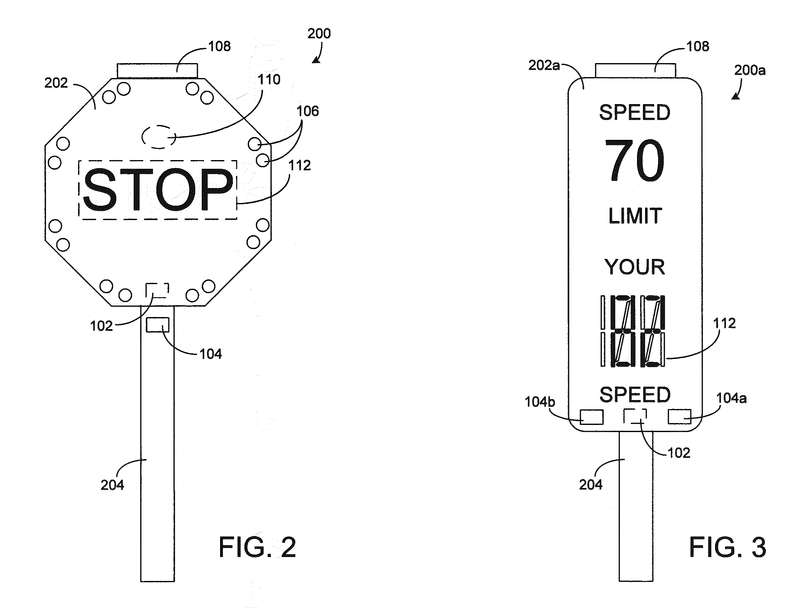
[0013]In the implementation of any traffic system, a designer must generally contend with issues of economics and environment. Mass-produced intelligent interactive vehicular signage has the potential to make a two-stop sign intersection nearly as safe as a conventional traffic light, which may cost fifty times as much, with less wasted time of drivers at the intersection, less wasted gasoline and less driver frustration. Seen another way, mass-produced interactive signs with intelligence can cost effectively be used in ten to one hundred times more locations as conventional signs and signals, potentially saving tens of thousands of lives and hundreds of thousands of injuries and vehicular collisions.

[0014]According to one embodiment of the present invention, a driver approaching a sign is not alerted if their vehicle is performing in accordance with the sign. If, for instance, a driver's speed is within prescribed limits and a sensor indicates that a vehicle is slowing properly for...


PUM


Abstract

A vehicular blind spot detection system (700) for alerting a driver of a motor vehicle to an object in the vehicle's blind spot, the system includes a first imaging device (707) used typically used to control vehicle lighting and that works to detect objects substantially forward of the vehicle and a second imaging device (709) typically used with a rear camera display (RCD) for detecting objects substantially rearward of the vehicle. A control unit (711) is coupled to the first imaging device (707) and second imaging device (709) that includes a graphic processing unit (713) for processing images captured by the first imaging device (707) and second imaging device (709) for detecting an optical flow of objects within the images so as to discriminate between vehicles and other objects entering the driver's blind spot.

Description

FIELD OF THE INVENTION[0001]The present invention relates generally to vehicular blind spot detection and more particularly to detecting blind spots using rear mounted and front facing imaging devices.BACKGROUND OF THE INVENTION[0002]A blind spot monitor is a vehicle-based sensor system that detects other vehicles located to the driver's side and rear. Warnings can be visual or audible where increased warnings can indicate potentially hazardous lane changes. The detection of other vehicles in a driver's blind spot has typically been achieved both mechanically and electrically. Differing types of reflective mirrors have been used both inside and outside a vehicle for enhancing the driver's view so as to detect objects in the vehicles' blind spot. Electrical implementations for blind spot monitoring have included milliwave radar and rearward backing cameras located on the vehicle's outside mirrors, however, each of these systems are complex often requiring retrofit to existing vehicle...

Claims


Application Information

Patent Timeline
Patent Type & Authority Patents(United States)
IPC IPC(8): G08G1/16
CPCG01P1/08G08G1/04G08G1/052G08G1/095G08G1/096783
Inventor HOEK, STEVEN G.NEWTON, MARK W.
Owner GENTEX CORP
Why Eureka
Try Eureka